Unlock instant, AI-driven research and patent intelligence for your innovation.

Automated fluid handling system

a fluid handling system and automatic technology, applied in the field of automatic fluid handling system, can solve the problems of sample loss and time loss, serious disruption of the operation of automated fluid handling system, and sample destruction or other ways lost, so as to avoid unreliable and invalid results, avoid loss of valuable samples, and improve the operation process of the fluid handling system

Active Publication Date: 2018-10-16
CYTIVA SWEDEN AB
View PDF13 Cites 0 Cited by
  • Summary
  • Abstract
  • Description
  • Claims
  • Application Information

AI Technical Summary

Benefits of technology

This solution prevents unreliable results, avoids sample loss, and increases productivity by ensuring controlled resumption of operations, reducing the need for partial process restarts and minimizing time loss.

Problems solved by technology

During some phases of operation of such systems a disruption of the operation may be fatal in that the analysis results or process results may become unreliable and invalid, further the sample may be destroyed or in other ways lost.
Power failure is a common problem in many countries, even in laboratory environments, and may thus cause serious disruptions of the operation of automated fluid handling systems as mentioned above.
For example, in chromatography, if the power fails during the run, the injected sample may be lost and the entire run may have to be restarted which will lead to sample loss and time loss.
Further, the system throughput is reduced due to the need to restart the process.

Method used


Image

  • Automated fluid handling system
  • Automated fluid handling system
  • Automated fluid handling system

Examples


Embodiment Construction

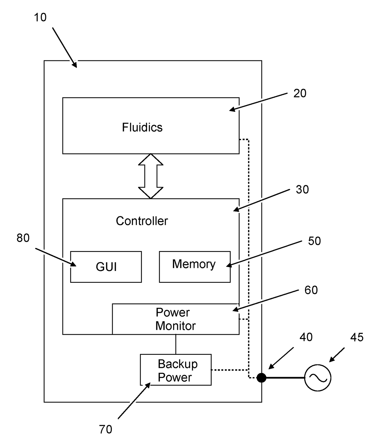
[0022]FIG. 1 schematically discloses a generic automated fluid handling system 10 according to the present invention. The fluid handling system 10 comprises a fluidics section 20, a controller 30 and a power source input 40 for connection to an external power source 45 for powering the system 10. The external power source 45 may be any conventional source of electrical power such as an electric power grid, a power generator, a solar power plant or the like. Under normal operation, the fluidics section 20 and the controller 30 are powered by the external power source 45 as indicated by dotted lines in FIG. 1, but in order to better handle failure of the external power source 45 the fluid handling system 10 further comprises a backup power source 70 for supplying back-up power to the controller 30 during situations of power failure.

[0023]The fluidics section 20 may be of any type as briefly discussed above, such as: liquid chromatography fluidics, filtration fluidics, biomolecular syn...


PUM

PropertyMeasurementUnit
poweraaaaaaaaaa
time thresholdaaaaaaaaaa
timeaaaaaaaaaa

Abstract

Automated fluid handling system comprising a controller arranged to control the operation of the fluid handling system in accordance with a predefined or user-defined operation process, the fluid handling system comprising a power source input for connection to an external power source, the fluid handling system comprising a back-up power source arranged to supply back-up power to the controller, wherein the controller is arranged to monitor the power source input andin response to a detected power shortage initialize suspend mode of operation powered by the back-up power source, and during suspend mode saving information relating to status of the operation process at the time of power shortagein response to a detected power up initialize a boot procedure comprising a verification if the boot procedure is initialized following a suspend mode or not:if the boot procedure is not initialized following a suspend mode, then proceed according to normal boot procedure to enable start of a new operation process, andif the boot procedure is initialized following a suspend mode, then perform a second verification based on the saved information to determine if the suspended operation process may be resumed or not.

Description

CROSS-REFERENCE TO RELATED APPLICATIONS[0001]This application is a filing under 35 U.S.C. 371 of international application number PCT / EP2014 / 069399, filed Sep. 11, 2014, which claims priority to Indian application number 2709 / DEL / 2013, filed Sep. 13, 2013, the entire disclosures of each of which are hereby incorporated by reference.FIELD OF THE INVENTION[0002]The present invention relates to an automated fluid handling system, and in particular to an automated liquid chromatography system with a system-restore arrangement for restoring operation process after a power shortage.BACKGROUND[0003]In modern laboratories across the globe, fully or at least partially automated laboratory apparatuses or fluid handling systems are becoming more and more frequent. Compared to manually controlled systems, automated systems enable researchers and laboratory staff to free up time to perform more high value work and / or tasks that cannot be automated. Moreover in many situations, automated control ...

Claims


Application Information

Patent Timeline
Patent Type & Authority Patents(United States)
IPC IPC(8): G01N35/00G01N30/88
CPCG01N30/88G01N35/00712
Inventor BHARGAV, ANOOPSRINIVASAN, JEGANATHANNABI, BABU RASOOL
Owner CYTIVA SWEDEN AB