Optical fiber cable

a technology of optical fiber and fiber optic cables, applied in the field of optical fiber optic cables, can solve problems such as deteriorating transmission characteristics, and achieve the effects of excellent transmission characteristics, interfering between bonding sections, and reducing the number of optical fiber strands

Active Publication Date: 2018-10-16
FURUKAWA ELECTRIC CO LTD
View PDF19 Cites 7 Cited by
  • Summary
  • Abstract
  • Description
  • Claims
  • Application Information

AI Technical Summary

Benefits of technology

[0006]The presently described embodiments were achieved in view of such problems. The object of these embodiments is to provide an optical fiber cable that includes intermittently bonded optical fiber ribbons and has excellent transmission characteristics.
[0010]According to an embodiment, when a plurality of the optical fiber ribbons are accommodated, the positions of the bonding section thereof in the longitudinal direction do not coincide with each other completely, and thus restraining force of each of the optical fiber ribbons is weak, preventing application of stress from being concentrated at one place.
[0012]Furthermore, the bonding-section positions of at least one pair of the optical fiber ribbons in the longitudinal direction do not overlap with each other so that interference between the bonding sections is suppressed and the restrain on the optical fiber strands can be further suppressed.
[0013]The presently described embodiments can provide an optical fiber cable that includes intermittently bonded optical fiber ribbons and has excellent transmission characteristics.

Problems solved by technology

More particularly, it has been found out that, when the positions of the connected sections of the optical fiber ribbons overlap with each other completely, the motion of the optical fiber ribbons, which configures the intermittently bonded optical fiber tape, is impeded, deteriorating transmission characteristics.

Method used


Image

  • Optical fiber cable
  • Optical fiber cable
  • Optical fiber cable

Examples


Embodiment Construction

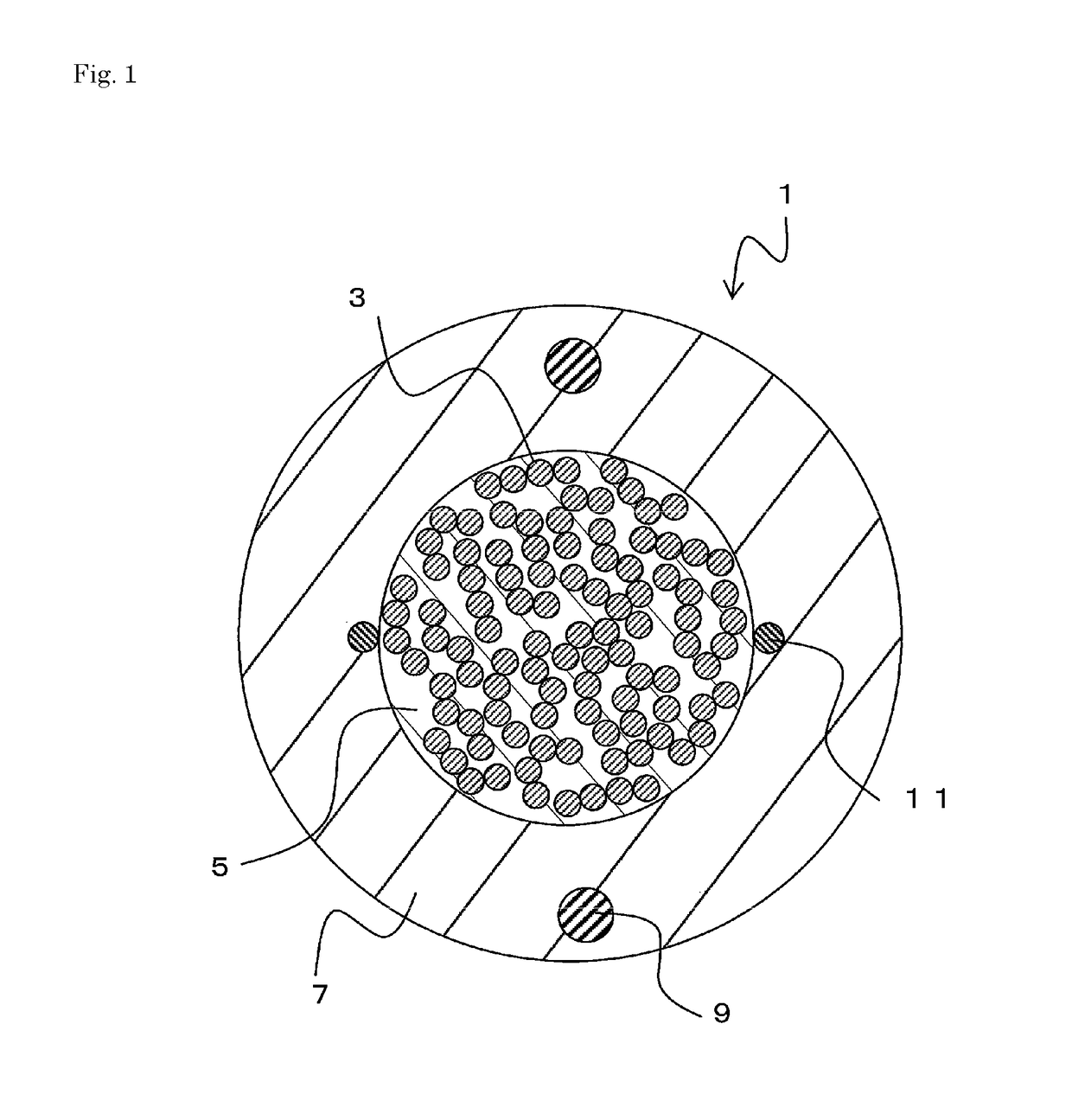
[0019]Hereinafter, embodiments of will be described with reference to the accompanying drawings. FIG. 1 is a cross sectional view showing an optical fiber cable 1. The optical fiber cable 1 mainly includes optical fiber ribbons 3, a buffer layer 5, a coat layer 7, tension members 9, ripcords 11, and so on.

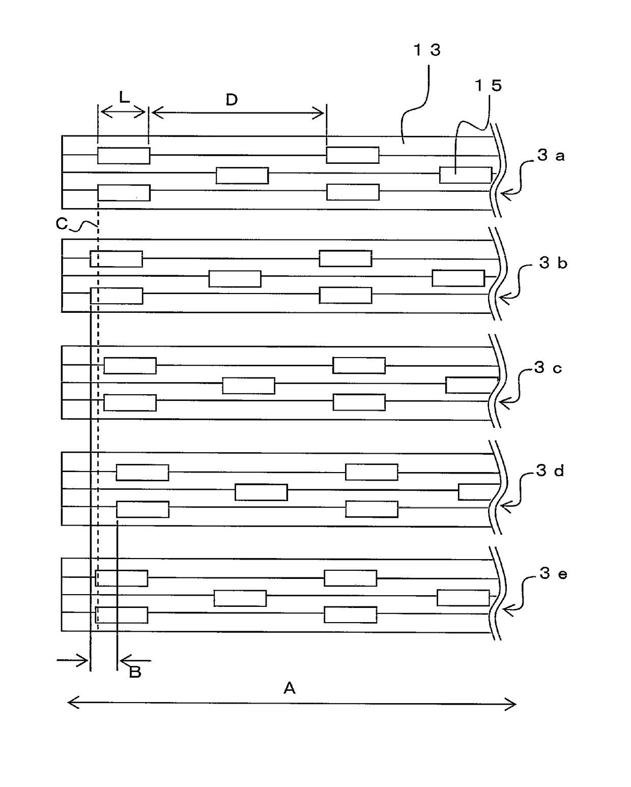
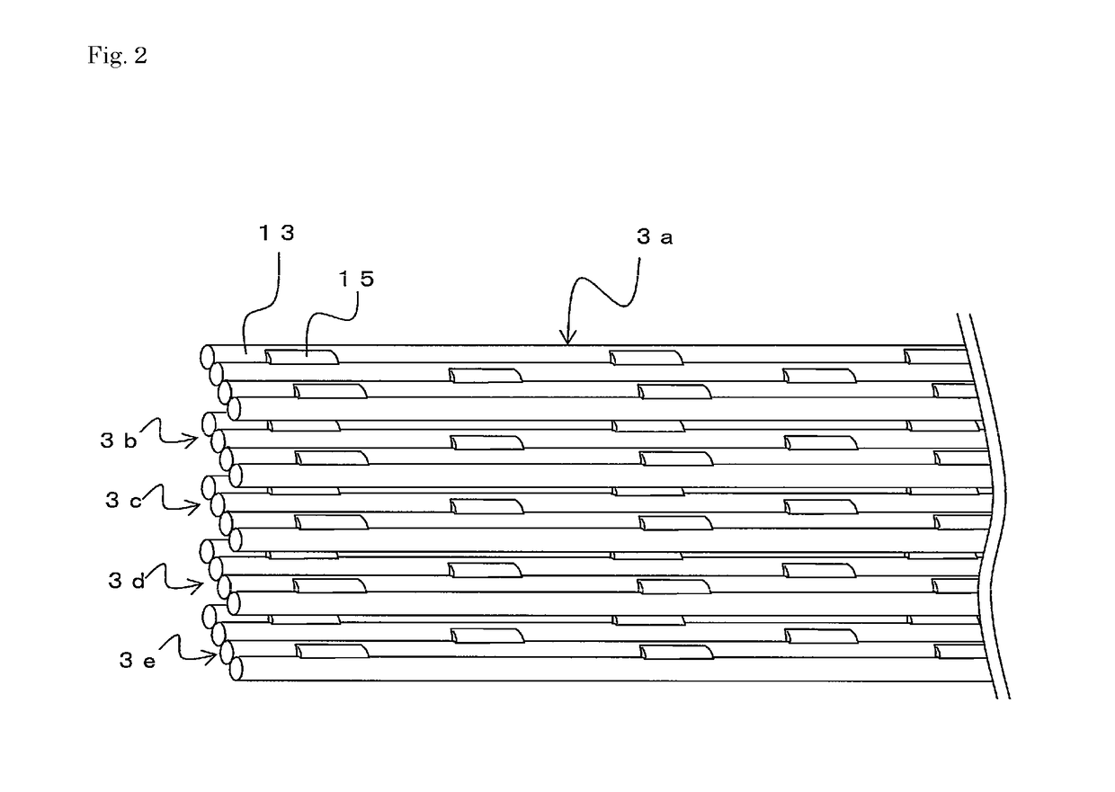
[0020]The optical fiber ribbon 3 is an optical fiber ribbon in which a plurality of optical fiber strands are arranged in parallel and integrated. The optical fiber ribbon 3 will be described in detail later.

[0021]The buffer layer 5 is provided on the outer periphery of the optical fiber ribbons 3. The buffer layer 5 protects the optical fiber ribbons 3 from external force and the like.

[0022]The coat layer 7 is formed on the outer periphery of the buffer layer 5. The coat layer 7 is a layer to coat and protect the optical fiber cable 1. The tension members 9 are provided inside the coat layer 7.

[0023]The tension members 9 are subjected to tensile force of the optical fiber cable 1....


PUM


Abstract

Optical fiber ribbons each comprise a plurality of optical fiber strands bonded in parallel. In the optical fiber ribbons, adjacent optical fiber strands are bonded by bonding sections that are intermittently bonded at prescribed intervals. The positions of the bonding section for all optical fiber ribbons are mutually offset in the longitudinal direction. In other words, the longitudinal-direction positions of the bonding section for the optical fiber ribbons never exactly match.

Description

TECHNICAL FIELD[0001]This disclosure relates to an optical fiber cable in which a plurality of optical fiber strands are bonded in parallel.BACKGROUND[0002]As an optical fiber for transmitting numerous data at high speed, an optical fiber ribbon in which a plurality of optical fiber strands are arranged and bonded in parallel is used for simple cable storage and operation. In some optical fiber ribbons, parallel optical fiber strands are fixed and bonded by resin over the full length thereof. In other optical fiber ribbons, optical fiber strands are bonded to each other intermittently, such as Japanese Unexamined Patent Application Publication No. 2010-8923, for example.[0003]With these intermittently bonded optical fiber ribbons, no large strain is given to the optical fiber ribbons when the optical fiber cable, which is packaged densely with optical fibers, is bent. This is because the optical fiber ribbon can move freely as a single core at the non-connected sections of the inter...

Claims


Application Information

Patent Timeline
Patent Type & Authority Patents(United States)
IPC IPC(8): G02B6/44
CPCG02B6/443G02B6/4403G02B6/44G02B6/441
Inventor HOSHINO, YUTAKAOKADA, NOBORU
Owner FURUKAWA ELECTRIC CO LTD
Why Eureka
Try Eureka