Non motorized omni directional walking system device

a walking system and non-motorized technology, applied in the field of non-motorized omni-directional walking systems, can solve the problems of many restrictions on the walking motion required by virtual reality images, large noise, and inconvenient use, and achieve the effect of simple structur

Active Publication Date: 2018-10-16
CHOI HAE YONG
View PDF17 Cites 7 Cited by
  • Summary
  • Abstract
  • Description
  • Claims
  • Application Information

AI Technical Summary

Benefits of technology

[0010]An aspect of the present invention provides a method so that a pedestrian is able to walk freely in accordance with the intention of the pedestrian and not in a predetermined direction but in all directions in 360 degrees and move diagonally without being power driven and / or without a roller, a motor driving the roller, a configuration of a belt, a floor, and an electric driving device.
[0011]According to an aspect of the present invention, a non motorized omni-directional walking system device is provided, which includes: a walking dish formed in any one of a circular shape, a semi-circular shape, and a polygonal shape; multiple rolling balls formed on the surface of the walking dish, in which a stop surface is formed at the center or on one side of the walking dish and an inclined surface is formed on the periphery of the walking dish, and the rolling ball is configured in a spherical shape with a radius of 1 to 50 mm, which has a precise curvature; multiple auxiliary balls constituted by multiple rolling balls on the surface of the walking dish and formed below the rotation ball so that the rolling ball smoothly rotates in all directions of 360 degrees in up, down, left, and right directions; a ball fixing device that fixes the auxiliary ball and the rolling ball so that they are not to be separated from predetermined positions while allowing the auxiliary ball and the rolling ball to rotate in all directions of 360 degrees in up, down, left, and right directions; and a ball fixing table formed below the ball fixing device, which is used for joining the multiple ball fixing devices on the surface of the inclined surface at a predetermined interval to allow a user to walk in all direction in 360 degrees in forward, backward, left, and right directions according to a virtual reality or walking motion image based on a stop surface of the walking dish.
[0015]In addition, since the rotation ball has an effect of automatically adapting and rotating according to the walking speed and direction of the pedestrian without electric driving, instantaneous turning of a walking direction and a movement speed may be automatically changed.
[0016]Therefore, since the rotation ball moves according to the intentions of the pedestrian in terms of movement, stopping, and speed, the structure is simple and the pedestrian may move and walk in all angles in 360 degrees and in all directions including a diagonal direction, and the like without a driving device driven by power, such as a roller, a universal joint motor, or the like, and there is no limit in installation space.

Problems solved by technology

Since the person moves by power using an electric motor, a minute movement speed, adjustment, or the like is not natural and driving by the electric motor causes large noise and requires a soundproofing device which a complicated structure to prevent noise.
In addition, US 2009 / 0111670A is constituted by a friction sensor and a piezoelectric sensor (Mechanism for red using friction) on a floor, but only a walking position is retrieved, and the user can not obtain the movement effect of walking in place.
There are many limitations on operation elements, such as stopping the motor by turning off a switch, so that there are many restrictions on the walking motion required by the virtual reality image and inconvenient in use.
In addition, the complicated driving device by the motor is noisy, which limits the installation place such as an apartment, an office, or the like and / or requires a complicated device to eliminate such noise.

Method used


Image

  • Non motorized omni directional walking system device
  • Non motorized omni directional walking system device
  • Non motorized omni directional walking system device

Examples


Embodiment Construction

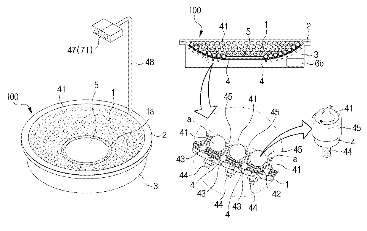
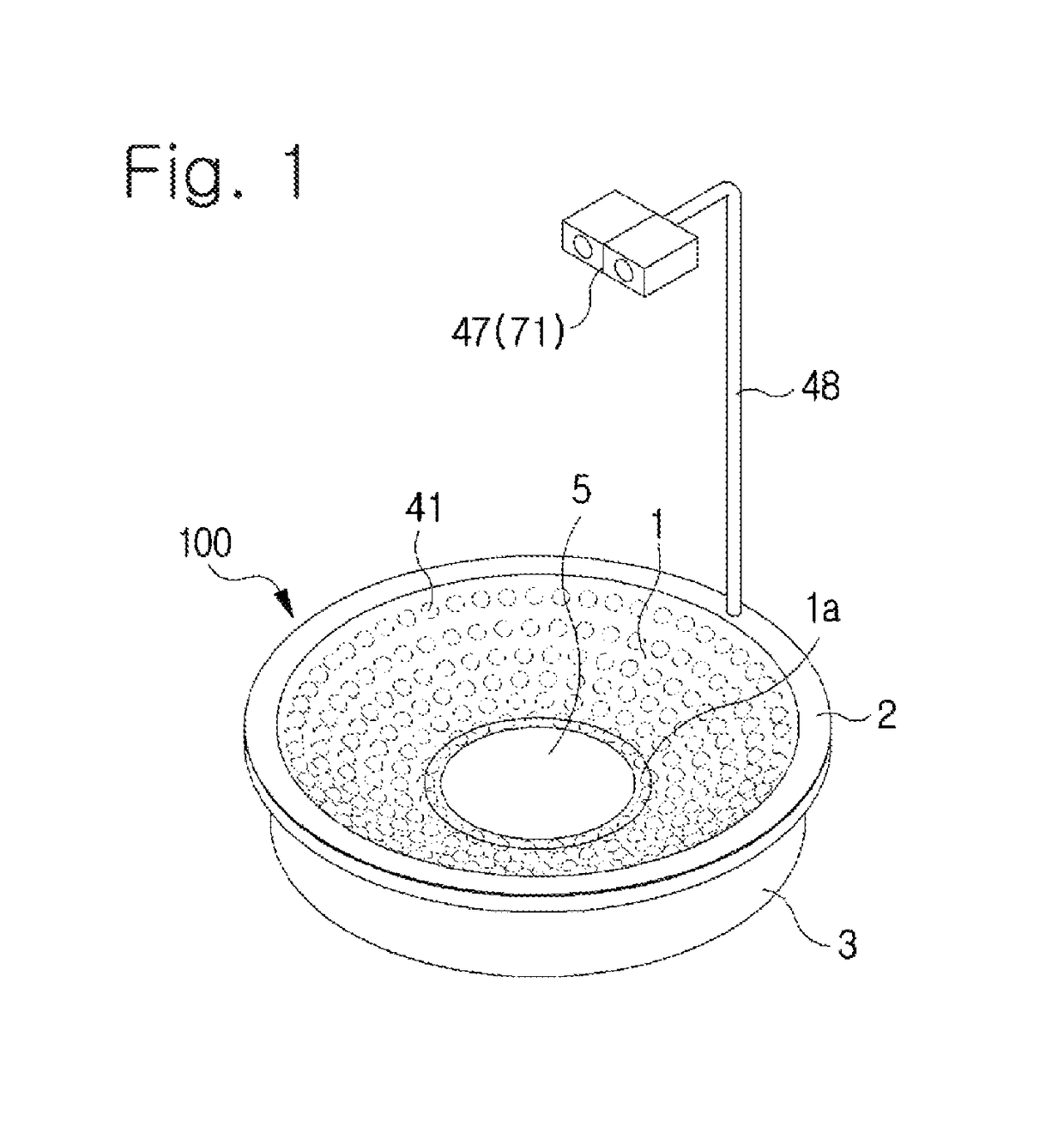
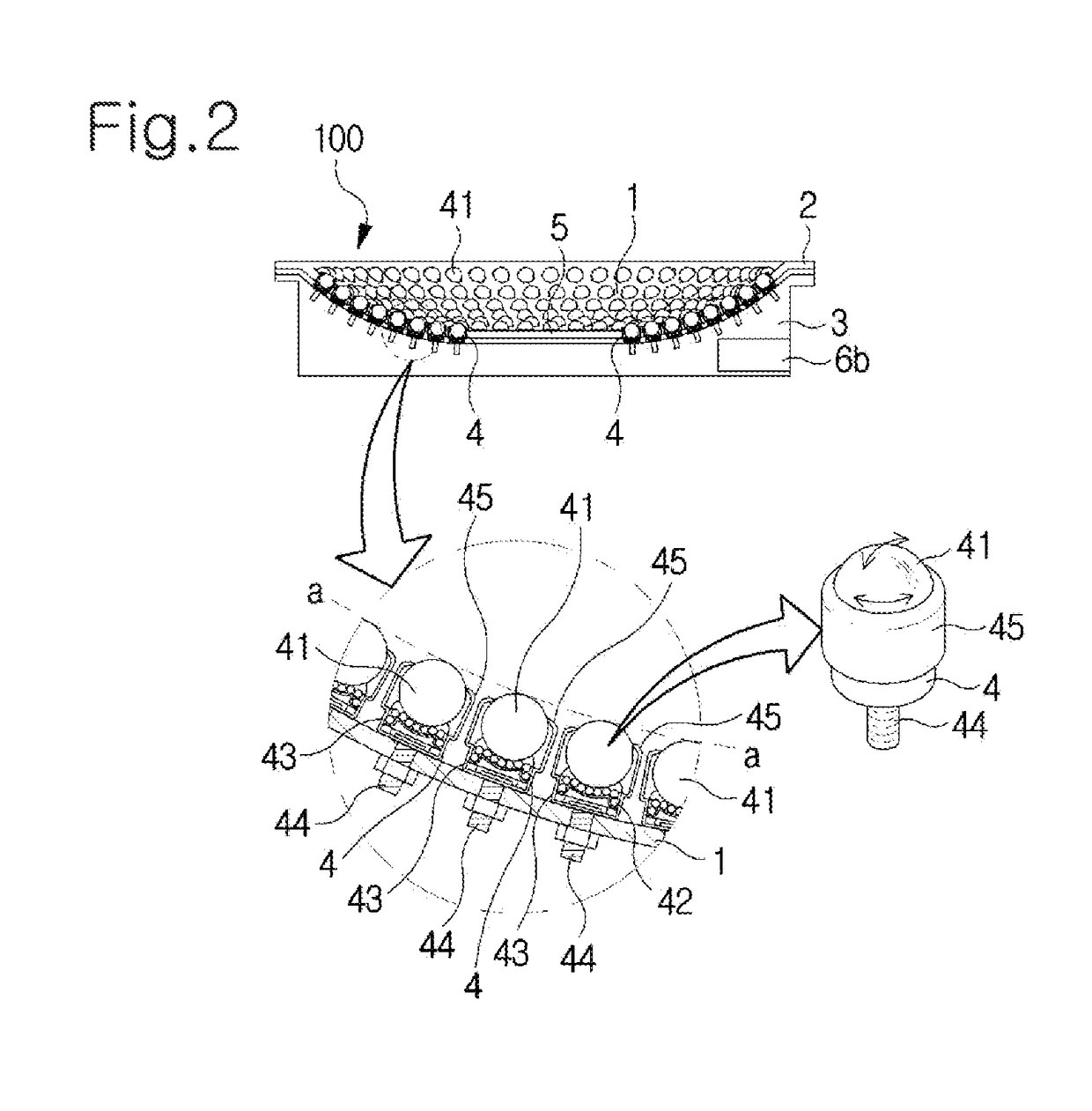
[0027]As illustrated in FIGS. 1 and 2, a non motorized omni-directional walking system device includes a walking dish 100 having an inclined surface 1 formed in the periphery thereof and a dish or a semi-dish shape formed by a flat surface at the center or on one side, a rolling ball 41 structure in which multiple rolling balls 41 are formed on the inclined surface 1 and are rolled in all 360 degree directions, which include left, right, front, and rear diagonal line directions, an auxiliary ball (42) structure which is configured with the lower part of the rolling ball (41) structure and with a lower part of each of the multiple ball fixing devices 4, and a sensor (43) structure which is configured in the lower part of the auxiliary ball structure 42 as necessary.

[0028]The shape of the walking dish 100 may be in various shapes, for example, in a circular shape, a semi-circular shape, a polygonal shape, and the like according to the purpose of the invention. That is, the inclined pl...


PUM


Abstract

A walking system that includes a walking dish formed in any one of a circular shape, a semi-circular shape, and a polygonal shape; a rolling ball formed on an upper surface of a ball fixing device; multiple auxiliary balls having multiple rolling balls on the surface of the walking dish and formed below the rolling ball so that the rolling ball smoothly rotates in all directions in 360 degrees; the ball fixing device fixing the auxiliary ball and the rolling ball while allowing the auxiliary ball and the rolling ball to rotate in all directions in 360 degrees; and a ball fixing table formed with the ball fixing device for joining the multiple ball fixing devices on the inclined surface at a predetermined interval to allow a user to walk in all directions in 360 degrees according to a virtual reality or walking motion image.

Description

CROSS-REFERENCE TO RELATED APPLICATION(S)[0001]This application claims benefit of priority to Korean Patent Application No. 10-2016-0129469 filed on Oct. 7, 2016 in the Korean Intellectual Property Office, the disclosure of which is incorporated herein by reference in its entirety.BACKGROUND OF THE INVENTION[0002]The present invention relates to a non motorized omni-directional walking system which allows a user to walk in all viewing-angle directions while viewing a virtual reality image and a walking exercise image, and particularly, includes a motor, a servo motor, a conveyor belt, a rotating ball structure without a folded floor structure.DESCRIPTION OF RELATED ART[0003]A virtual reality image refers to a device that provides images in all visual directions, e.g., in 360°, and provides virtual reality images in all desired directions of the user to a screen of a computer or the like while walking. Accordingly, the user should be able to walk in a limited position in any desired ...

Claims


Application Information

Patent Timeline
Patent Type & Authority Patents(United States)
IPC IPC(8): G06F3/01A63B69/00
CPCG06F3/011A63B69/0035G06F2203/012A63B2220/31A63B2220/803A63B2220/13A63B2022/0271A63B2071/0638A63B2209/08A63B2220/20A63B2220/40A63B2220/56A63B2220/807A63B2220/89A63B2230/01A63B22/18A63B24/0087A63B71/0622A63B2209/00
Inventor CHOI, HAE-YONG
Owner CHOI HAE YONG
Why Eureka
Try Eureka