Suspension control apparatus for vehicle and control apparatus for damping-force adjustable shock absorber
a control apparatus and vehicle technology, applied in the direction of shock absorbers, instruments, cycle equipments, etc., can solve the problems that so-called “clattering noise”, cannot always be fully suppressed, etc., to achieve the effect of suppressing the generation of abnormal nois
- Summary
- Abstract
- Description
- Claims
- Application Information
AI Technical Summary
Benefits of technology
Problems solved by technology
Method used
Image

Examples
first embodiment
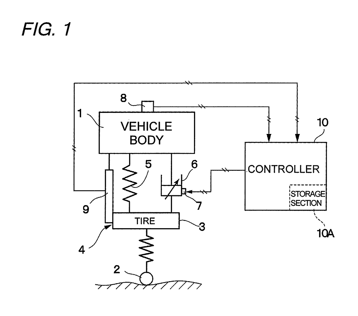
[0027]FIGS. 1 to 8 illustrate the present invention. In FIG. 1, a vehicle body 1 corresponding to a body of a vehicle is illustrated. Below the vehicle body 1, for example, right and left front wheels and right and left rear wheels (hereinafter, collectively referred to as wheels 2) are provided. Each of the wheels 2 includes a tire 3 and the like.
[0028]A suspension apparatus 4 is interposed between the vehicle body 1 and the wheel 2. The suspension apparatus 4 includes a suspension spring 5 (hereinafter, referred to simply as “spring”5) and a damping-force adjustable shock absorber 6 (hereinafter, referred to simply as “shock absorber”6) provided between the vehicle body 1 and the wheel 2 in parallel to the spring 5. Note that, in FIG. 1, the case where the single suspension apparatus 4 is provided between the vehicle body 1 and the wheel 2 is illustrated as an example. However, the number of the suspension apparatuses 4 is, for example, four in total so that each of the suspension...
second embodiment
[0075]The second embodiment is characterized in the following configuration. An acceleration sensor 41 on the so-called unsprung side is provided to the vehicle on the tire 3 side. The vertical vibration acceleration on the wheel 2 (tire 3) side is detected by the acceleration sensor 41. Then, the detected signal is output to the controller 10.
[0076]Subtraction processing is performed by a computing section 42 illustrated in FIG. 10. Specifically, an acceleration signal on the unsprung (wheel 2) side, which is detected by the acceleration sensor 41, and the acceleration signal on the sprung (vehicle body 1) side, which is detected by the acceleration sensor 8, are subjected to subtraction processing to calculate a relative acceleration between the sprung side and the unsprung side. In a subsequent integration operation section 43, the relative acceleration between the sprung side and the unsprung side is integrated to obtain a vertical relative velocity between the vehicle body 1 an...
third embodiment
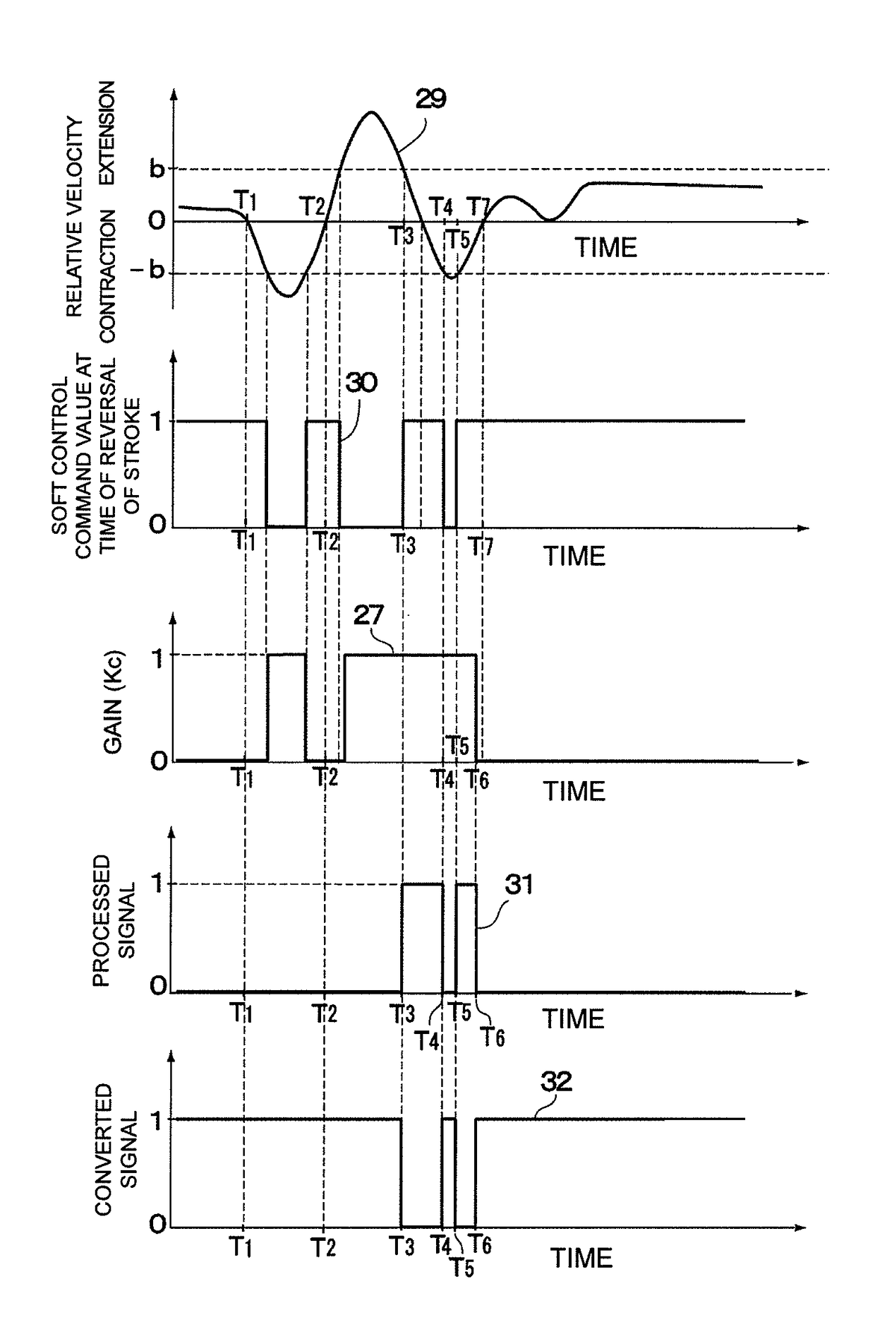
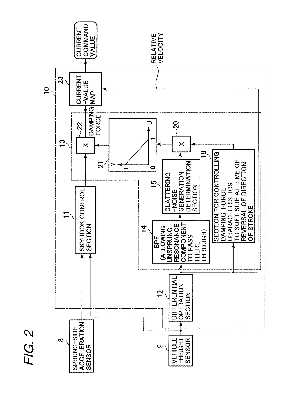
[0089]In the third embodiment configured as described above, the sprung acceleration signal detected by the acceleration sensor 8 and the unsprung acceleration signal detected by the acceleration sensor 41 are subjected to the subtraction processing in the computation section 42 to obtain the relative acceleration between the sprung side and the unsprung side. Then, the clattering-noise control section 51 performs the bandpass filter processing on the signal of the damping force, which is calculated based on the damping-force map 52, according to the relative velocity between the vehicle body 1 and the wheel 2, which is obtained from the relative acceleration, to thereby determine whether or not the clattering noise is generated. According to the result of determination, the clattering-noise control section 51 performs the skyhook control and the control for switching the damping-force characteristics to the soft side at the time of reversal of the direction of the stroke, which is ...
PUM
 Abstract
Description
Claims
Application Information
 - R&D
- Intellectual Property
- Life Sciences
- Materials
- Tech Scout
- Unparalleled Data Quality
- Higher Quality Content
- 60% Fewer Hallucinations
Browse by: Latest US Patents, China's latest patents, Technical Efficacy Thesaurus, Application Domain, Technology Topic, Popular Technical Reports.
© 2025 PatSnap. All rights reserved.Legal|Privacy policy|Modern Slavery Act Transparency Statement|Sitemap|About US| Contact US: help@patsnap.com