Handheld applicator suitable for gun valve containers

a technology for gun valve containers and applicators, which is applied in the field of hand-held applicators suitable for gun valve containers, can solve the problems of attachment release, difficult to predict and control the dosing of compound with such handheld systems, and inaccurate compound dosing, etc., and achieves easy and intuitive use, excellent ergonomics, and elimination of complex and costly assembly steps.

Active Publication Date: 2018-10-23
SOUDAL
View PDF28 Cites 11 Cited by
  • Summary
  • Abstract
  • Description
  • Claims
  • Application Information

AI Technical Summary

Benefits of technology

[0021]We have found that the handheld applicator of the present invention offers excellent ergonomics to the user, and is extremely easy and intuitive to use for non-experienced end users. A particularly advantageous feature is that the handheld applicator provides not only for a handle surface for an action by the finger or several fingers, but also for a grip surface for contact with the palm of the hand. By having both surfaces integrated in the same applicator, it is avoided that the action on the applicator would strain the connecting attachment between the applicator and the container. This significantly and usually eliminates the risk that during the action the handheld applicator becomes unintentionally disconnected from the container, and compound would unintentionally be released in rather uncontrollable and for the user possibly dangerous directions. This brings a significant extra safety feature.
[0022]The handheld applicator offers the further advantage that it may be produced as one single piece, eliminating any complex and costly assembly steps, and therefore may be available at low cost. The applicants have further found that the handheld applicator may be designed such that the flow of compound may be controlled by putting more or less power on the applicator, and this without any adjustment screw. It was further found that the excellent ergonomics of the handheld applicator and its design may offer the user improved aiming and dosing capabilities, which broadens its suitability over a wider range of applications. The assembly may thus for instance be suitable also for the filling of smaller crevices with PU-foam, and allows reducing the amount of excess compound which is typically applied and which needs to be removed later and thus ends up as waste. This reduces the amount of aftercare work required and brings a higher efficiency in material use.
[0023]The assembly of the present invention, as compared to the disclosure in WO 2009 / 147250 A2, brings the advantage that the important parts of the handheld applicator are integrated, i.e. the fixed part and the moveable part, resulting in a handheld applicator which may be produced as one single piece. After production, it may thus be ready for direct assembly with the pressure container. The handheld applicator of WO 2009 / 147250 A2 on the other hand consists of various different parts, and requires a significant and complex assembly operation as part of the production and supply chain. In addition, the handheld applicator of WO 2009 / 147250 A2, seals on top of the valve stem, whereby the applicator according to the present invention preferably seals along the side of the valve stem, more preferably around the grommet or rubber of the valve, as explained below. Because the valve stem may be somewhat moved by deformation of the valve cup after closing off the container, the assembly of WO 2009 / 147250 A2 is more prone to unintentional and / or premature leakage of container contents, resulting in loss of useful product, extra cleaning and after care, and possibly even safety and industrial hygiene concerns.
[0027]The production process according to the present invention is simple and fast, and is able to produce the handheld applicator and the assembly at a low cost.

Problems solved by technology

The compound dosing with such handheld systems is however rather inaccurate, and such a system is therefore more suitable for filling large crevices or cavities, such as those wider than 2 cm.
They are therefore specific and only suitable for containers equipped with a straw valve.
They therefore retain the disadvantage that the dosing of the compound remains difficult to predict and control, e.g. because the position of the side openings at the bottom of the stem is unpredictable with respect to the direction of tilting.
The disadvantage with such systems is that during the action of the hand, the connecting attachment between the applicator and the container is strained, and usually in a direction which creates a risk that the attachment would release and create a risk for unintentional release of compound.
After use, there remains thus little to no volume of compound which has been exposed to the atmosphere and may react, become rigid and impair the operation of the gun during a subsequent use.
Compound inside the gun may only become exposed to the atmosphere for the short time required for exchanging a container on the dispensing gun.
These dispensing guns are usually more complex and expensive and are typically reused several times after replacing the previous empty container with a fresh and full one.
Many gun valves are also not made for being tilted.
Gun valves are not designed for being tilted, and are thus not provided with a stem extension or with a screw thread section.
Consequently, straw valve containers cannot be used with equipment designed for gun valve containers.
The screw thread connection is incompatible with gun valves, and the known handheld applicators designed for straw valve containers are unable to operate on a gun valve container.
The difficulty with this design is that fastening of the handheld applicator onto or off the valve stem needs to be performed very carefully, as any unintentional tilting of the valve during this operation would cause premature and unintentional spillage of compound, and any damage to the valve may create a safety hazard.
One drawback with this proposal is that the assembly of the applicator with the container provides the same ergonomics of a conventional handheld applicator assembly during use.
A further drawback is that removal of the safety plate is irreversible.
Once broken off, the security against inadvertent opening cannot be reinstalled.
Another drawback is that the handheld applicator of US 2007 / 0181610 A1 does not comprise a compartment for storing e.g. protecting gloves, useful for the user for protecting his hands against contact with the container content.
A drawback of this applicator is that it comprises at least 4 components which need to be produced separately and subsequently require assembly.
A further drawback is that it requires an adapter which is suitable for the type of valve it is intended for, and an assembled applicator is only suitable for one type of valve.
Another drawback is that the trunk comes out below the hand, which is inconvenient for an accurate aim.
A further drawback is that the removal of the safety lip is irreversible.
Once broken off, the security against inadvertent opening cannot be reinstalled.
Another drawback is that the handheld applicator of WO 2009 / 147250 does not comprise a compartment for storing an accessory object, e.g. protecting gloves, useful for the user for protecting his hands against contact with the container content.

Method used


Image

  • Handheld applicator suitable for gun valve containers
  • Handheld applicator suitable for gun valve containers
  • Handheld applicator suitable for gun valve containers

Examples


Embodiment Construction

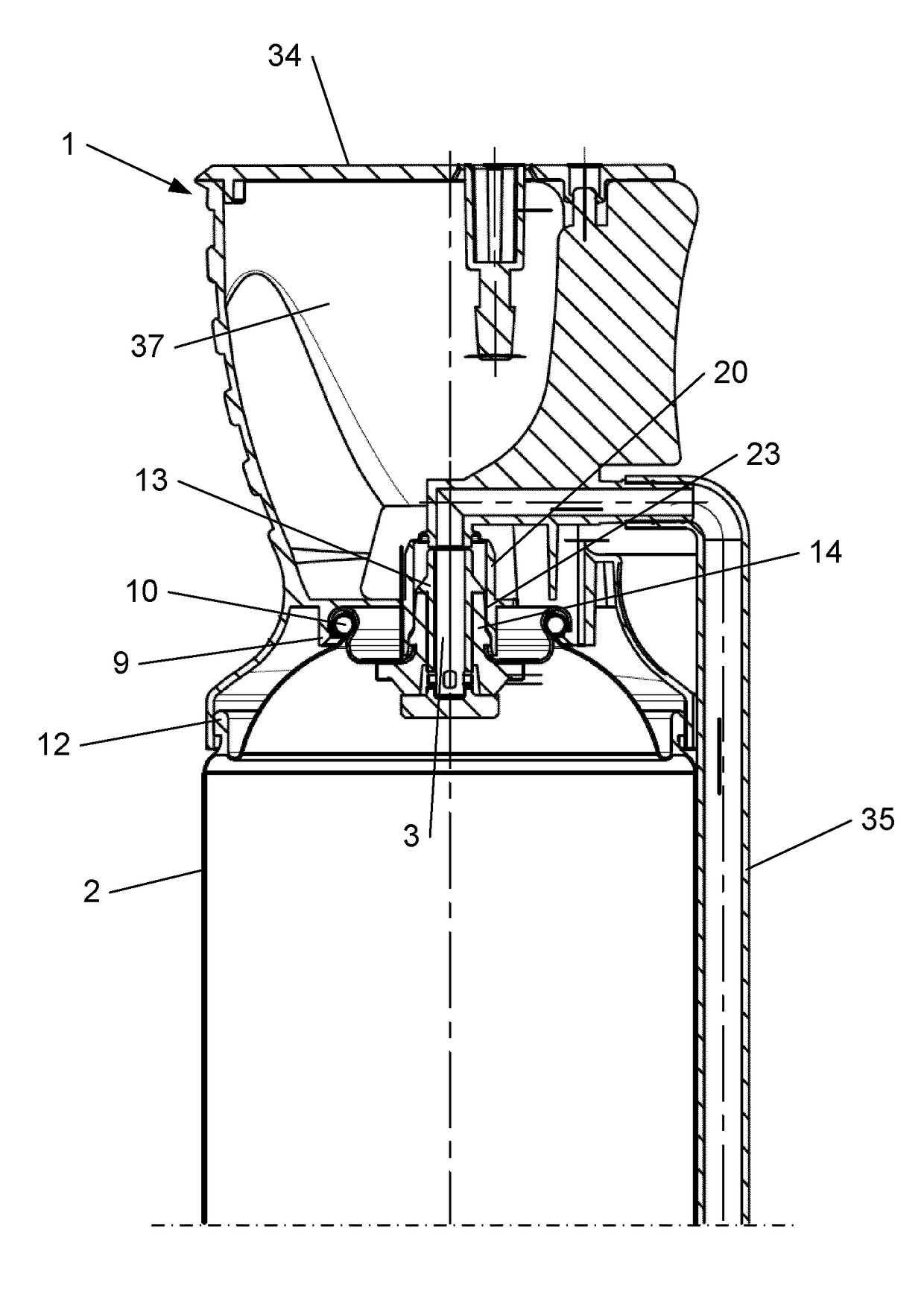
[0034]The containers for compounds under pressure are typically designed as cylinders. The bottom is usually closed off by flanging a concave bottom plate onto the cylinder. The top of the cylinder is typically closed off by flanging on a convex head plate, with therein a central opening through which the container may be filled with its content. This opening is then typically closed off with a valve through which the container content may be released using the pressure which is built up inside the container. This container valve is typically also flanged onto the container head. This valve flange connection is formed by shrinking the container valve onto the container head, thereby typically at the same time closing off the container after it has been filled.

[0035]At room temperature, the pressure inside a filled and ready-to-use container is typically about 5 bar gauge. The containers are typically able to remain intact up to a pressure of 18 bar gauge, and are designed to not bur...


PUM

PropertyMeasurementUnit
surface areaaaaaaaaaaa
pressureaaaaaaaaaa

Abstract

An improved handheld applicator is provided, fitted into an assembly onto a pressure container which is equipped with a gun valve and containing a viscous compound suitable for forming a silicone paste, a polyurethane (PU) foam, or a glue, the applicator being producible in one single injection molding step and providing in handheld use the ergonomics, the aiming and the dosing accuracy comparable to the use of the pressure container with a dispensing gun. Further provided is a process for the production of the applicator and of the assembly, as well as the use of the assembly for applying a compound from the pressure container with a handheld method.

Description

CROSS-REFERENCE TO RELATED APPLICATIONS[0001]This application is the entry into the United States of PCT Application No. PCT / EP2011 / 068203 filed Oct. 18, 2011 and claims priority from European Patent Application No, EP 10187929.4 filed Oct. 18, 2010, the entirety of each of which are hereby incorporated by reference.FIELD OF THE INVENTION[0002]The current invention relates to containers, cans or canisters containing a compound under pressure which is a high viscosity composition suitable for forming a silicone paste, a polyurethane (PU) foam, or a glue, in particular disposable containers, primarily those which are equipped with a gun valve such that the container may be coupled to a device, typically called a dispensing gun, for applying the compound. The compound is usually reactive or curable, may thus comprise one or more active components, and is suitable to form for example a sealant (e.g. a silicone paste), a polyurethane (PU) foam, or a two component glue. The invention is p...

Claims


Application Information

Patent Timeline
Patent Type & Authority Patents(United States)
IPC IPC(8): B65D83/16B65D83/40B65D83/20B65D83/22B65D83/30
CPCB65D83/16B65D83/206B65D83/22B65D83/303B65D83/40B65D83/226Y10T29/49826
Inventor HERMANS, MARCGEBOES, PETERVERVOORT, BARTDE GROOF, ERIK
Owner SOUDAL
Why Eureka
Try Eureka