Thermally isolated high intensity light source

a high-intensity light source and thermal isolation technology, applied in the direction of saving energy measures, construction fastening devices, light and heating apparatus, etc., can solve the problems of insufficient spectral output change, reduced bulb operating temperature, and complicated efforts to cool light sources in applications. , to achieve the effect of improving efficiency

Inactive Publication Date: 2018-10-30
SURNA
View PDF66 Cites 1 Cited by
  • Summary
  • Abstract
  • Description
  • Claims
  • Application Information

AI Technical Summary

Benefits of technology

[0010]Provided herein is a HID light source operating at improved efficiency for optimal light output and methods related thereto. The configuration of the light source includes an optically transparent sleeve that thermally insulates an insulative volume surrounding the bulb, thereby allowing the bulb to operate at a steady-state and optimal higher temperature while still being able to apply active cooling mechanisms to the fixture cavity and / or environment surrounding the bulb surface. Ensuring a higher steady-state bulb operating temperature provides for optimal spectral output from the HID bulb when active cooling is applicable to the fixture or encapsulating environment.
[0011]Furthermore, the high intensity discharge light source is configured to prevent potential harm to the surrounding environment by minimizing the release of heat generated by the bulb, as well as shielding the environment from falling debris in the event of a bulb failure. Accordingly, the systems and methods provided herein not only ensure a retention of spectral performance, but also have the added functional benefit of increasing safety and reducing adverse heating in an environment surrounding the light source.
[0012]The high intensity discharge light sources described herein may comprise a bulb; a thermally insulative and optically transparent sleeve that surrounds the bulb and is separated from the bulb by an insulating distance; and a spacer for creating an insulative volume between the bulb and the sleeve, such as a spacer clip, bumper, or integrated positioner at each end of the bulb, such as a relief feature. During use, the bulb and insulative volume reach a steady state operating temperature to maintain or enhance a spectral performance parameter. In an aspect, the steady state operating temperature is characterized as having a high temperature. In this context, high temperature refers to the configuration of the insulative sleeve provided herein that elevates temperature compared to conventional systems wherein heat dissipation out of the bulb to the surrounding environment is encouraged and facilitated, such as by active convective air flow over the bulb surface. In this context, the elevated temperature may be quantified in terms of a percentage increase compared to conventional systems without the sleeve, such as at least a 5%, 10%, or 20% increase in temperature, particularly during forced airflow introduction. The spectral performance parameter may be quantified in terms of an increase in photosynthetic photon flux density (PPFD) and / or a spectral shift. In an embodiment, the PPFD is increased by at least 5% compared to a corresponding system that does not include a sleeve as described herein. This increase in PPFD is attributed to an operating temperature increase that better matches bulb optimum operating temperature.

Problems solved by technology

This can complicate efforts to cool light sources in applications where heat build-up around the bulb is desirably avoided.
For example, if a HID light source is actively cooled, the bulb operating temperature may be reduced with an attendant spectral output change that is no longer optimal.
Heat build-up, however, associated with use of one or more HID light sources adversely impacts plant growth, particularly for plants positioned immediately below the HID light source.
Furthermore, the heat generated from the bulb can cause a bulb melt down or explosion, resulting in debris falling onto a plant canopy or other flammable material below the bulb, which in turn could result in fire.
Conventional systems that attempt to address certain of the above-referenced problems in the art suffer from fundamental disadvantages, including light fixtures that simply allow heat to escape to the environment.
That tube, however, is configured to provide heating to the environment and to not trap heat inside the envelope, and accordingly is fundamentally incompatible with light sources having an insulative sleeve that traps heat next to the bulb to maintain a relatively high operating temperature.
That system, however, dissipates heat from the light bulb by pushing or pulling air through the sleeve.
This directly cools the bulb, having an adverse impact on the ideal operating temperature of the bulb and an attendant decrease in spectral output.
There is no teaching or suggestion of insulating the resultant bulb to control the bulk bulb operating temperature, such as under cooling conditions.
However, there is no teaching or suggestion as to the tube being thermally insulative, and the bulbs described therein are fluorescent lamps.

Method used


Image

  • Thermally isolated high intensity light source
  • Thermally isolated high intensity light source
  • Thermally isolated high intensity light source

Examples


example 1

nsity Discharge Light Source

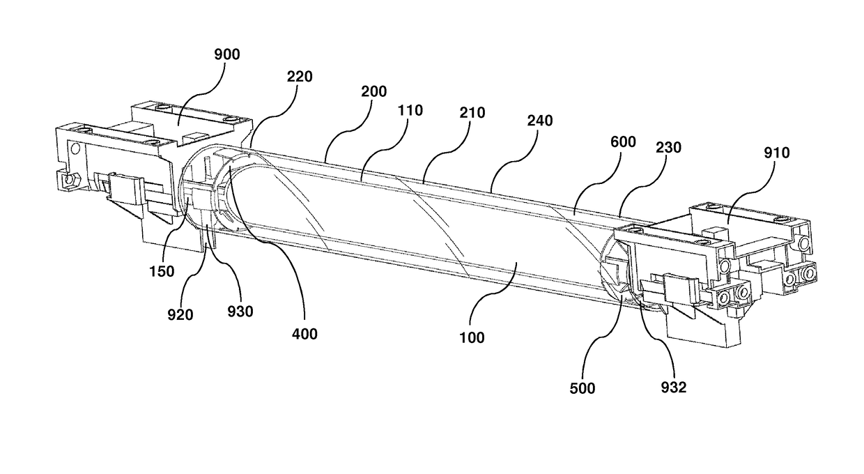
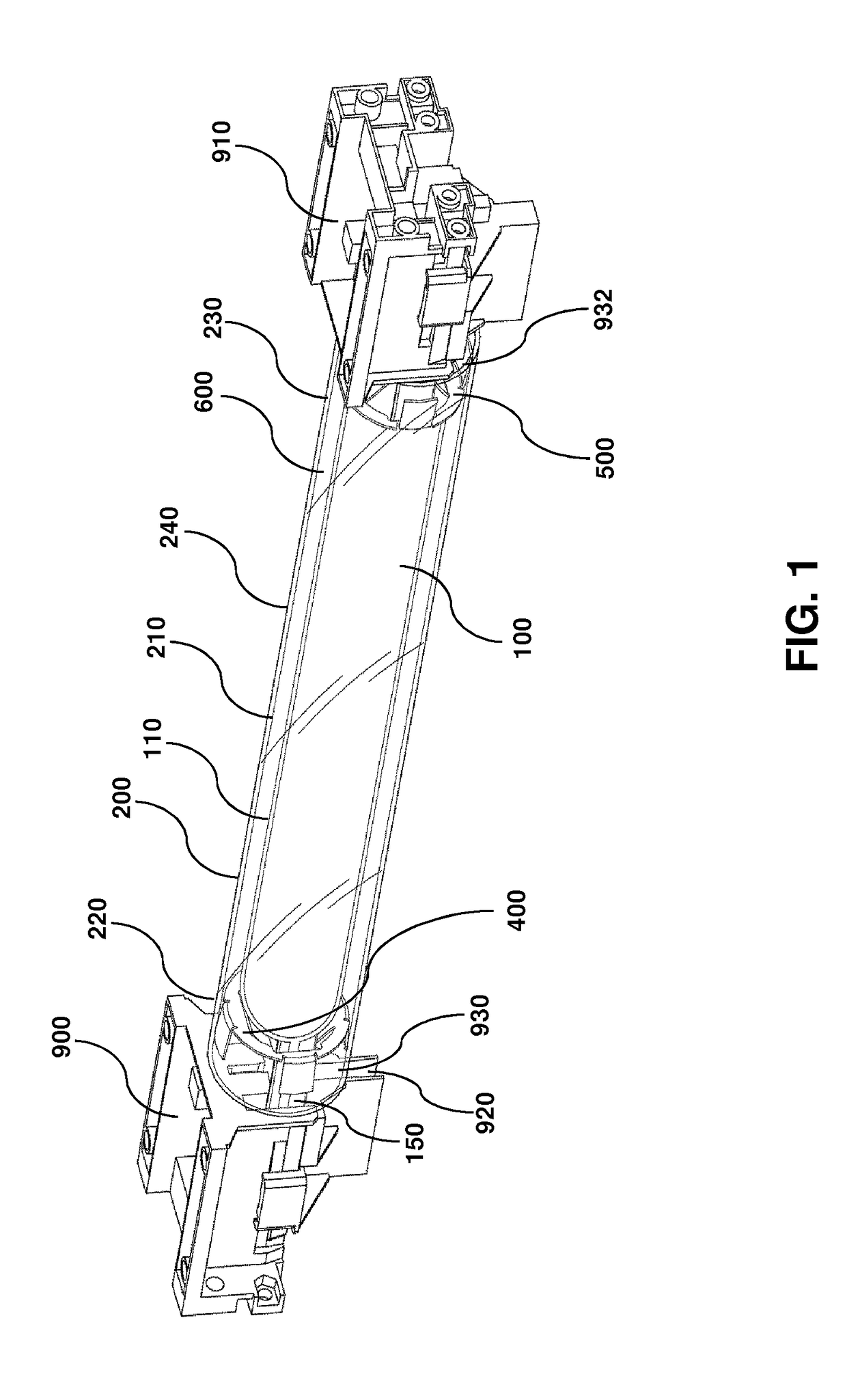
[0073]Provided herein are specially configured optical light sources, wherein a bulb is positioned within a sleeve, such as a quartz sleeve. This facilitates an increase in light intensity provided to the plant canopy, allows cooling of the light source without spectrum shift by flowing air, including cooled air, over an exterior facing surface of the sleeve, and increases safety in the event of a catastrophic light source failure such as a melt-down or explosion. Examples include an optical light source comprising a quartz sleeve that is separated from the outer surface of a bulb by a separation distance, wherein an inner surface of the quartz sleeve and the outer surface of the bulb define an insulative volume. This configuration is beneficial because the insulative volume increases an operating temperature of the bulb during use compared to an equivalent bulb without the quartz sleeve. This increase can occur even while the rest of the light source is ...

example 2

ip

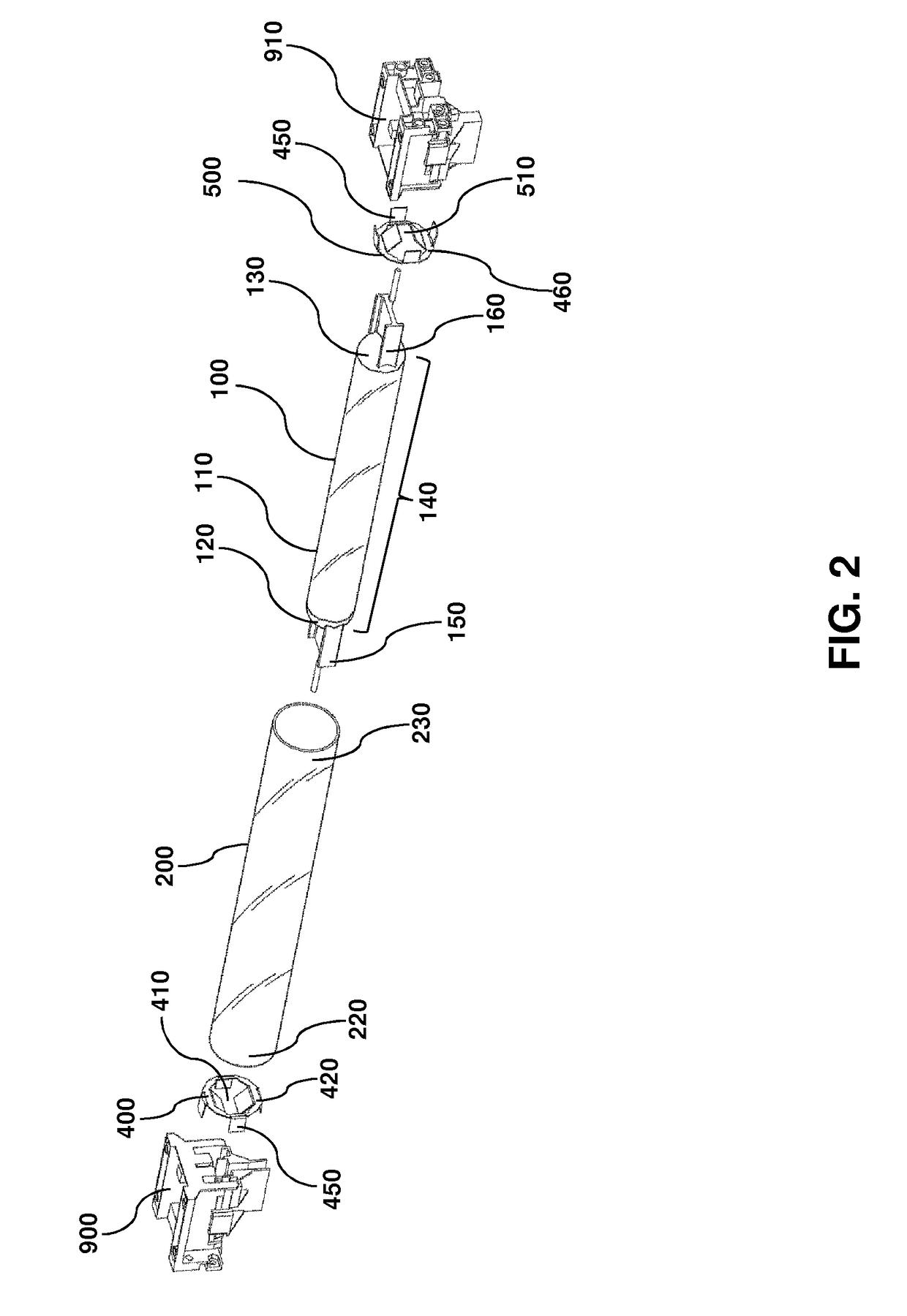
[0081]The spacer clips provide an insulative volume around the bulb and prevent the bulb from touching the sleeve and may be conveniently configured to handle any of a wide range of bulb and sleeve geometries and sizes. An exemplary embodiment is shown in FIGS. 4-5. The spacer clips are formed by a ring member 420 with an outer edge 430, an inner edge 440, and protruding members 450 that may be circumferentially and evenly spaced at four positions along an outer facing surface 460. At certain opposibly facing positions around the ring member 420, such as two positions as illustrated, the protruding members 450 are in the form of spring tabs 470 having two members, an outer member 480 and an inner member 490. In this manner, the outer and inner protruding members provide reliable connection and spacing between the light source and sleeve.

example 3

Efficiency and Spectral Performance

[0082]The configuration of the sleeve provides improved spectral performance. By thermally isolating the bulb from the surrounding environment and retaining heat in close proximity, the efficiency of the light source increases. Quartz is particularly useful due to its optical clarity properties. FIGS. 7-10 are plots of the spectral output for different bulb wattages with and without a quartz sleeve for different times.

[0083]FIGS. 11-19 demonstrate that the addition of a quartz sleeve increases PPFD on a target area. The purpose of the experiments is to observe the spectral performance of an HPS bulb in a standard industry optical reflector with and without a quartz sleeve installed. Referring to FIGS. 11-19, the maximum PPFD is located at the center of the 4 foot by 4 foot target area. The target distance (from reflector to bottom) is 68 inches. The voltage to the ballast is 240 VAC. A photometer is used to collect light readings on the target area...


PUM


Abstract

Provided herein is a high intensity discharge light source having a thermally insulative and optically transparent sleeve for maintaining or enhancing a spectral performance parameter. The configuration of the sleeve provides an insulative volume that allows an elevated steady state operating temperature to be reached, even when the light source is cooled. The sleeve is also configured to withstand a bulb failure event, thereby protecting the surrounding environment from falling debris. Also provided herein are methods for dissipating heat from the light source without adversely affecting the bulb operating temperature or the enhanced spectral performance parameter.

Description

CROSS-REFERENCE TO RELATED APPLICATIONS[0001]This application is a U.S. National Stage Application under 35 U.S.C. § 371 of International Application No. PCT / US2015 / 057216, filed Oct. 23, 2015, which claims the benefit of and priority to U.S. Pat. App. No. 62 / 117,302 filed Feb. 17, 2015 and 62 / 078,267 filed Nov. 11, 2014, and is a continuation-in-part of PCT App. No. PCT / US2015 / 028803 filed May 1, 2015 which claims the benefit of and priority to U.S. Pat. App. Nos. 62 / 078,267 filed Nov. 11, 2014, 62 / 052,890 filed Sep. 19, 2014 and 61 / 987,905 filed May 2, 2014, each of which are hereby individually incorporated by reference in their entirety to the extent not inconsistent herewith.BACKGROUND OF INVENTION[0002]Provided are high intensity discharge (HID) light sources that provide high efficiency and quality illumination via tight thermal control of the light sources without adversely heating the environment surrounding the light sources. Applications for the high intensity discharge l...

Claims


Application Information

Patent Timeline
Patent Type & Authority Patents(United States)
IPC IPC(8): H01J61/34F21V29/67A01G9/26F21V29/505E05C1/12F21V29/503F21V29/83H01J61/50
CPCE05C1/12A01G9/26F21V29/505H01J61/34F21V29/67H01J61/50F21V29/503F21V29/83A01G9/249A01G7/045Y02P60/14
Inventor KEEN, STEPHENWHITAKER, TODDJOHNSON, JORDANPEARSON, CHRISSCHULTZ, BRADY
Owner SURNA
Why Eureka
Try Eureka