
Thermoforming packaging machine with a top film forming station

a packaging machine and top film technology, applied in packaging machines, metal working apparatus, packaging under special atmospheric conditions, etc., can solve the problems of top film, lower film, and risk of fouling or contaminating products

Active Publication Date: 2018-11-06
MULTIVAC SEPP HAGGENMULLER GMBH & CO KG
View PDF17 Cites 2 Cited by
  • Summary
  • Abstract
  • Description
  • Claims
  • Application Information

AI Technical Summary

Benefits of technology

[0007]The object of the present invention is to improve a thermoforming packaging machine with a top film forming station, so that the above-described disadvantages may be eliminated.
[0013]A top film transport device may be provided by clamp chains to securely and accurately transport the top film without creases.
[0015]The traverse system may comprise struts, for example, four struts to stably and accurately move the trays and to thereby require little space laterally beyond the films.
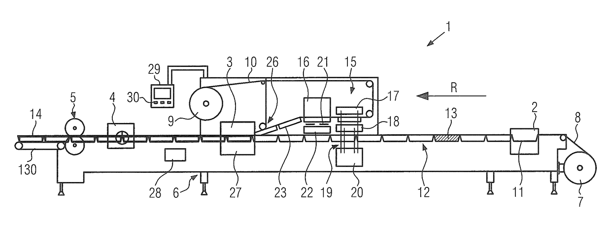
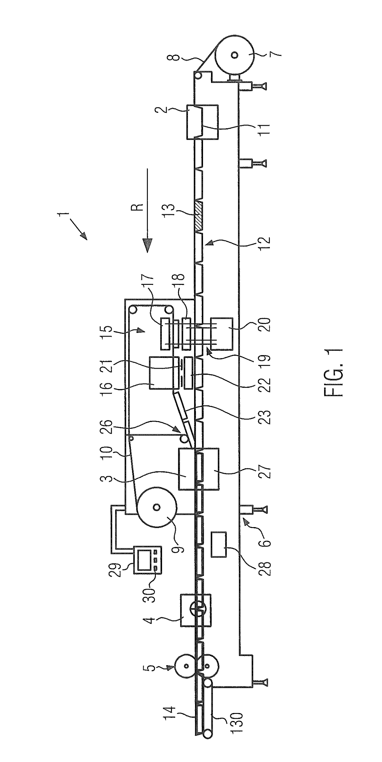
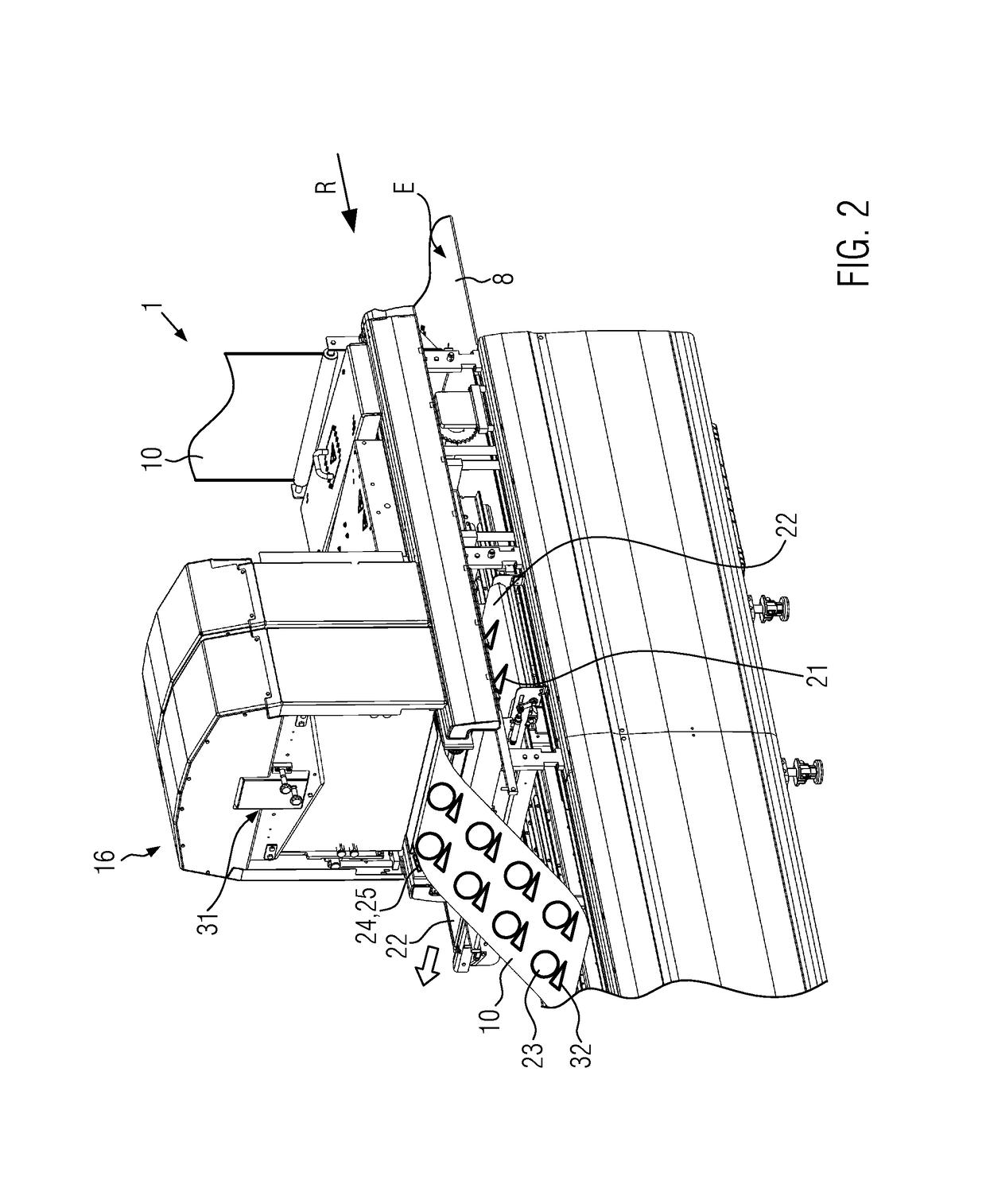
[0017]The method according to the invention for operating the thermoforming packaging machine can be characterized in that a lifting mechanism is disposed below a film transport plane of the thermoforming package machine and transmits its lifting motion via a traverse system to lower and upper tools of a top film forming station which are disposed above the lower film transport plane. It is despite the slightly higher mechanical effort in this manner possible to reduce or even eliminate the risk of fouling or contaminating the products that are located on the lower film due to mechanical abrasion or oil from the lifting mechanism.
[0018]It may be advantageous if, after forming the top film in the top film forming station, cutting or punching the top film in a top film cutting station occurs prior to the top film being fed to a sealing station. The top film, still being uncut in the top film forming station, can be formed or deepdrawn in a structurally simple manner, since no previously introduced openings must be specially sealed.

Problems solved by technology

A disadvantage of prior art is that the risk of fouling or contaminating the products, the top film, and the lower film is given, for example, due to mechanical abrasion, grease, or oil on the drive unit or on other moving parts of the lifting mechanism.

Method used


Image

  • Thermoforming packaging machine with a top film forming station
  • Thermoforming packaging machine with a top film forming station
  • Thermoforming packaging machine with a top film forming station

Examples


Embodiment Construction

[0028]The invention will now be described with reference to the drawing figures, in which like reference numerals refer to like parts throughout. For purposes of clarity in illustrating the characteristics of the present invention, proportional relationships of the elements have not necessarily been maintained in the drawing figures.

[0029]The following detailed description of the invention references specific embodiments in which the invention can be practiced. The embodiments are intended to describe aspects of the invention in sufficient detail to enable those skilled in the art to practice the invention. Other embodiments can be utilized and changes can be made without departing from the scope of the present invention. The present invention is defined by the appended claims and the description is, therefore, not to be taken in a limiting sense and shall not limit the scope of equivalents to which such claims are entitled.

[0030]FIG. 1 shows a schematic side view of a thermoforming...


PUM

PropertyMeasurementUnit
lifting forceaaaaaaaaaa
distanceaaaaaaaaaa
closing forcesaaaaaaaaaa

Abstract

A thermoforming packaging machine with a top film forming station, wherein the forming tool upper part and the foaming tool lower part of the top film forming station are disposed above a transportation plane of a lower film. One of the forming tool upper part or the forming tool lower part are operably connected to a lifting mechanism by a traverse system. The lifting mechanism is disposed below the transportation plane of the lower film. The traverse system transfers a lifting force from the lifting device to one of the forming tool upper part or lower part through the transportation plane of the lower film.

Description

CROSS-REFERENCE TO RELATED APPLICATIONS[0001]This application claims priority to European Patent Application Number 14151966.0 filed Jan. 21, 2014, to Elmar Ehrmann, currently pending, the entire disclosure of which is incorporated herein by reference.FIELD OF THE INVENTION[0002]The invention relates to a thermoforming packaging machine and to a method for operating same.BACKGROUND OF THE INVENTION[0003]A forming station for thermoforming trays into a film web is known from DE 197 345 13 A1. The forming station comprises a lifting mechanism for raising and lowering both the forming tool lower part disposed below the film web as well as the forming tool upper part disposed above the film web. The forming tool upper part is connected via a traverse system to the lifting mechanism. The forming tool lower part is driven directly by the lifting mechanism.[0004]DE 10 2009 020 892 A1 discloses a tray sealer with a forming station for a top film to form the latter to become a lid prior to s...

Claims


Application Information

Patent Timeline
Patent Type & Authority Patents(United States)
IPC IPC(8): B65B31/02B65B61/06B65B47/04B65B65/02B65B7/01B65B61/08B65B7/16
CPCB65B31/02B65B7/01B65B7/164B65B47/04B65B65/02B65B31/021B65B61/08B65B61/065B65B7/16B26D7/18B26F1/40
Inventor EHRMANN, ELMAR
Owner MULTIVAC SEPP HAGGENMULLER GMBH & CO KG
Learn More