Power forwarding via a powered device

a power forwarding and powered device technology, applied in data switching current supply, data switching network, data switching details, etc., can solve the problem of insufficient overhead communication and processing compared to load complexity, and achieve the effect of reducing connection requirements, simplifying poe-powered devices, systems and methods

Active Publication Date: 2018-11-06
SIGNIFY HLDG BV
View PDF14 Cites 1 Cited by
  • Summary
  • Abstract
  • Description
  • Claims
  • Application Information

AI Technical Summary

Benefits of technology

[0010]It is an object of the present invention to implement simpler PoE-powered devices, systems, and methods for a serial load system at reduced connection requirements.
[0013]In a preferred embodiment, said power switching unit is configured to enable power forwarding only after said powered device is fully powered. By enabling power forwarding only after said powered device is fully powered, the preferred embodiment provides for a more robust PoE environment. That is, due to the delay in each stage, the powered devices get activated one by one, hence avoiding a huge incrush current of multiple devices.
[0014]In a further preferred embodiment, said powered device is configured to detect whether the first port receives power from a second powered device based on whether said first port receives power without prior power negotiation. In a further preferred embodiment, said powered device is configured increase its power consumption with a slew rate that is lower than or equal to a predefined maximal slew rate if said powered device detects that the first port receives power from a second powered device. A first powered device arranged down the chain from a second powered device (i.e., the first powered device is coupled to a power sourcing equipment of said Power-over-Ethernet network not directly, but only via the second powered device) is preferably able to detect that it is chained, because said first powered device receives power without prior negotiation. This information is useful because the first powered device can thus ramp up its power consumption slowly, preferably in small steps so as to avoid overpowering of the powered device. Thereby, the system sequentially powers up in an efficient manner from the first device being connected to the power source equipment directly. In a further option, the power switching unit may be adapted to deactivate the output port if it determines that the remaining power amount is not enough. This ensures that sufficient power is always provided to subsequent load devices.

Problems solved by technology

However, in the new application field of lighting systems or similar load systems with often small loads with low local computing and communication requirements, sometimes the overhead of communication and processing compared to the load complexity is inappropriate.

Method used


Image

  • Power forwarding via a powered device
  • Power forwarding via a powered device
  • Power forwarding via a powered device

Examples


second embodiment

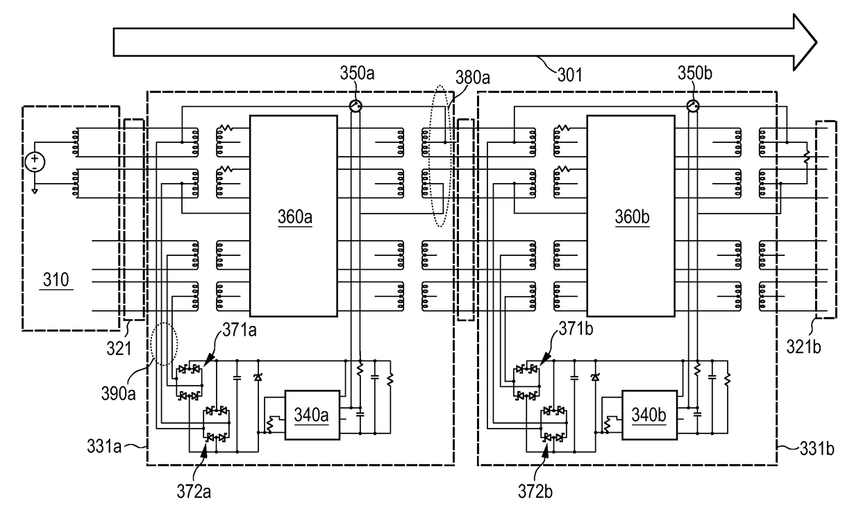
[0057]A second embodiment is shown and described in FIG. 5 showing a system 500 with a bidirectional power routing alternative indicated by arrow 501, which may be referred to as a “switched power bus”. Arrow 501 highlights the bidirectional energy flow direction which allows for a flexible wiring sequence.

[0058]In system 500, input and output ports may be used vice versa allowing for an error-free installation. In addition, using the input and output ports interchangeably offers the possibility to power PD 531a from two sides via lines 521a1 and 521a2. The switched bidirectional solution is described in more detail in the following.

[0059]Characteristics of the first solution (i.e., the switched unidirectional bus) essentially remain. Elements 5xx of system 500 correspond to like-numbered elements 3xx of system 300. However, in the switched bidirectional solution, power is accepted from either side via line 521a1 or via line 521a2.

[0060]As a mere design choice, two power switching u...

first embodiment

[0062]In contrast to the first embodiment, in the switched bidirectional solution, the two bridge rectifiers are not assigned to all pairs on one side, but are assigned to the “main” pairs on both sides. Consequently, powering may be applied from either side, rendering the connection sequence irrelevant. The detection and switching action is just like the one described with reference to FIGS. 3 and 4.

[0063]An exemplary realization of power switching units 350a, 350b, 550a1, 550a2 is illustrated by FIGS. 6 and 7. The power switching units can be realized in multiple ways. As one choice, a relay (such as, e.g., a Single Pole Single Throw, SPST, or a Double Pole Single Throw, DPST) may be used.

[0064]As another choice, solid state switches may be employed. An example based on MOSFETs will be described in the following. In particular, a bidirectional MOSFET switch 650a may be used as illustrated by FIG. 6.

[0065]Since the polarity of the input signal is not guaranteed (due to the fact tha...


PUM


Abstract

The present invention relates to a powered device (331a, 331b, 531a) with two interfacing connections. The powered device (331a, 331b, 531a) comprises power switching units (350a, 350b, 550a1, 550a2) for forwarding the data signal as well the power received on the input to the output. Forwarding may be based on a detection of the powering state of the PD. In another embodiment, the Power-over-Ethernet input / output ports function bi-directionally, thereby allowing the user to daisy-chain devices in any direction. As power switching units, relays or solid-state power switches may be used.

Description

CROSS-REFERENCE TO PRIOR APPLICATIONS[0001]This application is the U.S. National Phase application under 35 U.S.C. § 371 of International Application No. PCT / EP2015 / 064869, filed on Jun. 30, 2015, which claims the benefit of European Patent Application No. 14180295.9, filed on Aug. 8, 2014. These applications are hereby incorporated by reference herein.FIELD OF THE INVENTION[0002]The invention relates to a powered device, a Power-over-Ethernet network system, a method of power forwarding via a powered device, and a computer program product.BACKGROUND OF THE INVENTION[0003]Power-over-Ethernet (PoE) is a standard to supply power to detached data equipment and peripherals (like routers, switches, printer spoolers etc.) through the same wire or network connection that is already used to connect these to the Ethernet. Currently, discussions are coming up to make use of the same standard for all kinds of low power loads such as, e.g., lighting equipment (sensors, switches, light sources e...

Claims


Application Information

Patent Timeline
Patent Type & Authority Patents(United States)
IPC IPC(8): H04L12/40H05B37/02H04L12/28H04L12/10
CPCH04L12/40045H05B37/0263H04L12/2838H04L12/10H05B47/185
Inventor RADERMACHER, HARALD JOSEF GUNTHERWENDT, MATTHIASVAN GOOD, DAVE WILLEMYSEBOODT, LENNART
Owner SIGNIFY HLDG BV
Why Eureka
Try Eureka