Crusher with cutter assembly and cutter thereof

a technology of cutter and cutter body, which is applied in the field of crushers, can solve the problems of screw or threaded hole being prone to loose threads, and achieve the effects of preventing the shaking of the crusher cutter, preventing shaking, and enhancing working efficiency

Active Publication Date: 2018-11-13
KUN SHENG MACHINE
View PDF14 Cites 74 Cited by
  • Summary
  • Abstract
  • Description
  • Claims
  • Application Information

AI Technical Summary

Benefits of technology

[0006]The major object of the present invention is to provide a crusher with a cutter assembly and cutters thereof for being detachably disposed on the cutter base, and an arrangement of a single crusher cutter may be changed so that the crusher cutter may be replaced when being damaged. A corner portion and an abutting recess positionably abut against each other to precisely position each other, and a force between the corner portion and the abutting recess can be counterbalanced through the corner portion and the abutting recess abutting against each other. A conical wall of a hourglass-shaped through hole and a conical head of a first screw member tightly abut against each other so that the crusher cutter is stably assembled on the cutter base to prevent the crusher cutter from shaking and increase working efficiency. In addition, the crusher cutter assembly may have a cover body to further fix the crusher cutter so as to prevent shaking and elevate working efficiency, and the crusher cutter assembly may be used in cooperation with a pushing board to increase the efficiency of crushing materials.

Problems solved by technology

However, when the cutters are adjusted and screwed repeatedly, a screw or a threaded hole is prone to having stripped threads.

Method used


Image

  • Crusher with cutter assembly and cutter thereof
  • Crusher with cutter assembly and cutter thereof
  • Crusher with cutter assembly and cutter thereof

Examples


first embodiment

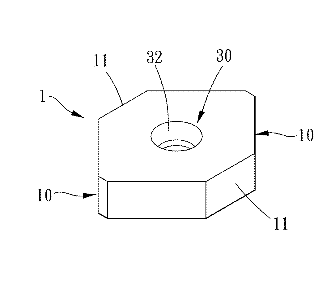
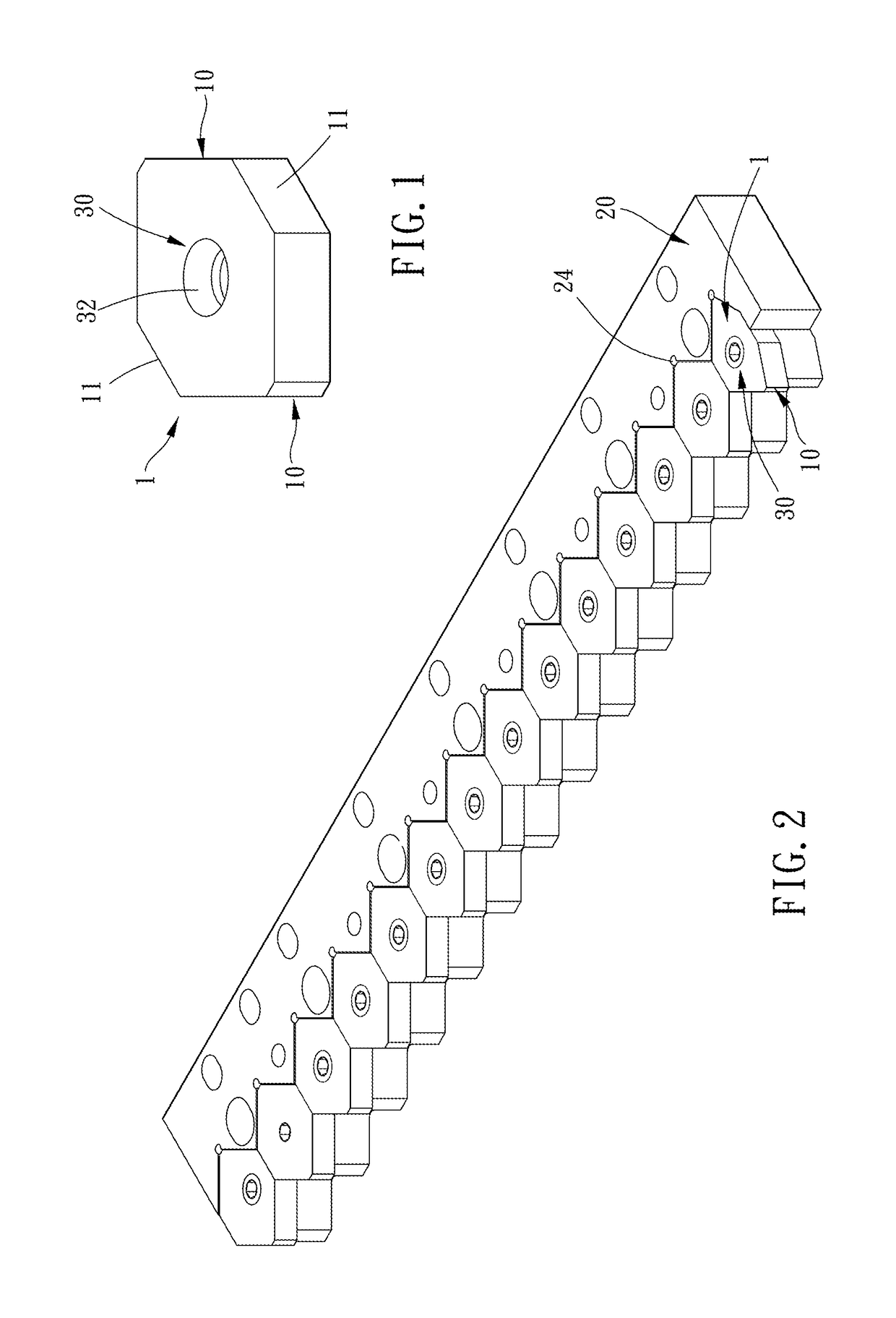
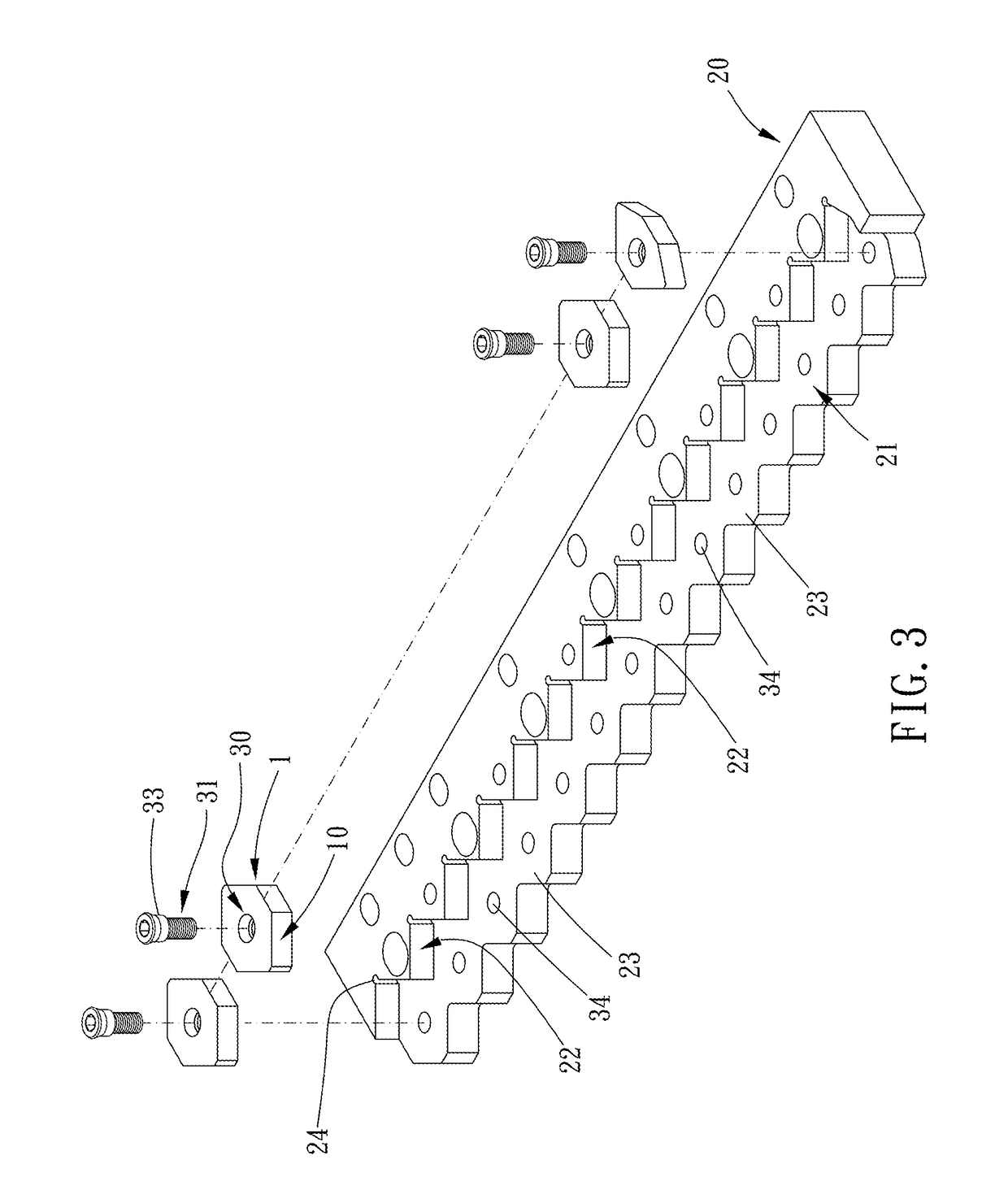
[0018]Please refer to FIGS. 1 to 3 for the present invention. The crusher cutter 1 is provided for being assembled on a cutter base 20 of a crusher. The cutter base 20 has a plurality of receiving slots 21, and each said receiving slot 21 includes an abutting recess 22 steppedly recessed on a surface of the cutter base 20 and a bottom portion 23 with a difference with respect to the surface of the cutter base 20. The crusher cutter 1 includes two corner portions 10 and two abutting portions 11.

[0019]The two corner portions 10 are disposed on two opposite sides of the crusher cutter 1 along a first direction respectively. The corner portion 10 is for being inserted into the abutting recess 22 and detachably fixed on the cutter base 20. At least two sides of the corner portion 10 abut against the abutting recess 22. When the crusher cutter 1 is assembled on the cutter base 20, the corner portion 10 and the abutting recess 22 can abut against each other to position each other.

[0020]In ...

second embodiment

[0025]Please refer to FIGS. 4 and 5 for the present invention. A crusher cutter 1a may include a middle layer 12 and two outer layers 13 on two opposite sides of the middle layer 12 respectively. The crusher cutter may be integrally formed with a material. One of the two outer layers 13 is fittingly engaged with the bottom portion of the receiving slot parallelly when the crusher cutter 1a is fixed on the cutter base. The two outer layers 13 are greater than the middle layer 12 in rigidity, and the two outer layers 13 are preferably made of tungsten steel or tungsten alloy. The middle layer 12 may include two positioning protrusions 14 disposed on two opposite sides of the middle layer 12 respectively, and the two outer layers 13 are disposed around the two positioning protrusion 14 on two opposite sides of the middle layer 12. Through the positioning protrusion 14, it is convenient for the user to positionably assemble the two outer layers 13 to the middle layer 12. The two outer l...


PUM


Abstract

A crusher includes a base, a cylinder pivoted to the base, cutting portions arranged on the cylinder. A crusher cutter assembly is further provided, including: a cutter base, for being assembled to the crusher, having receiving slots including an abutting recess and a bottom portion. A crusher cutter is further provided for assembling on the cutter base. The crusher cutter includes: two corner portions, disposed on two sides thereof, for being inserted in the abutting recess and fixed on the cutter base, two sides of the corner portion abutting against the abutting recess; two abutting portions, disposed on two opposite sides of the crusher cutter, for being positionably abutting against another crusher cutter; wherein when the crusher cutter is fixed on the cutter base, a part of the corner portion protrudes beyond the cutter base and is alternatively shifted with a part of the cutting portions.

Description

BACKGROUND OF THE INVENTION[0001]Field of the Invention[0002]The present invention relates to a crusher, and more particularly to a crusher with a cutter assembly and cutters thereof.[0003]Description of the Prior Art[0004]Usually, in a conventional crusher as disclosed in TWM449032, cutters are arranged on a cutter base, and an interval between each two cutters next to each other is adjusted through screwing. However, when the cutters are adjusted and screwed repeatedly, a screw or a threaded hole is prone to having stripped threads.[0005]The present invention has arisen to mitigate and / or obviate the afore-described disadvantages.SUMMARY OF THE INVENTION[0006]The major object of the present invention is to provide a crusher with a cutter assembly and cutters thereof for being detachably disposed on the cutter base, and an arrangement of a single crusher cutter may be changed so that the crusher cutter may be replaced when being damaged. A corner portion and an abutting recess posi...

Claims


Application Information

Patent Timeline
Patent Type & Authority Patents(United States)
IPC IPC(8): B02C4/20B02C4/28B02C18/18
CPCB02C4/20B02C18/18B02C4/286B02C2018/188
Inventor TSAI, CHAO-FA
Owner KUN SHENG MACHINE
Why Eureka
Try Eureka