Quartz magnetometer having a quartz resonant plate with a broaden distal end for enhanced magnetic sensitivity

a quartz resonant plate and quartz resonant technology, applied in piezoelectric/electrostrictive/magnetostrictive devices, piezoelectric/electrostrictive/magnetostrictive devices, instruments, etc., can solve the problems of poor sensitivity and moderate detection limits above 1 t in the prior art of silicon resonant magnetometers, and achieve the greatest bending moment, the effect of maximizing the force and keeping the width relatively narrow

Active Publication Date: 2018-11-13
HRL LAB
View PDF13 Cites 9 Cited by
  • Summary
  • Abstract
  • Description
  • Claims
  • Application Information

AI Technical Summary

Benefits of technology

[0022]The plate need not necessarily be trapezoidal. What is important is that (a) the cantilevered plate have a certain width at or near its free end and (b) that the width of the plate at or near where the plate is supported be less than said certain width. With a cantilever design where one side is anchored and the other is free, it is better to maximize the force at the free end to obtain the greatest bending moment. The width is kept relatively narrow at the anchor side to maximize the bending stress.

Problems solved by technology

Prior art involving silicon resonant magnetometers suffer from poor sensitivity and moderate detection limits above 1 μT.
Additionally, prior art silicon resonators are known to exhibit high temperature dependence, resulting in low stability of the measurement, whereas quartz resonators can be manufactured in various temperature-insensitive crystal cuts (AT cuts and SC cuts are preferred).
High drive currents (>1A) prevent widespread use in portable and low power devices.
The material of choice does not lend this prior art device to be easily integrated with electronics or other sensors.
While silicon devices can easily be integrated with on-chip electronics, they are prone to large frequency-temperature drifts.
Prior art often requires external and often separate drive and detection schemes which increases the complexities and noise.
SOA magnetometers are forced to compromise between small volume / low power and detection sensitivity.
Simply widening the entire quartz plate to increase the Lorentz force at the tip while maintaining a rectangular shape is not effective as the bending strain is independent of the plate width (the Lorentz force and the plate stiffness increase in proportion with each other, offsetting the effect of increased wtip).

Method used


Image

  • Quartz magnetometer having a quartz resonant plate with a broaden distal end for enhanced magnetic sensitivity
  • Quartz magnetometer having a quartz resonant plate with a broaden distal end for enhanced magnetic sensitivity
  • Quartz magnetometer having a quartz resonant plate with a broaden distal end for enhanced magnetic sensitivity

Examples


Embodiment Construction

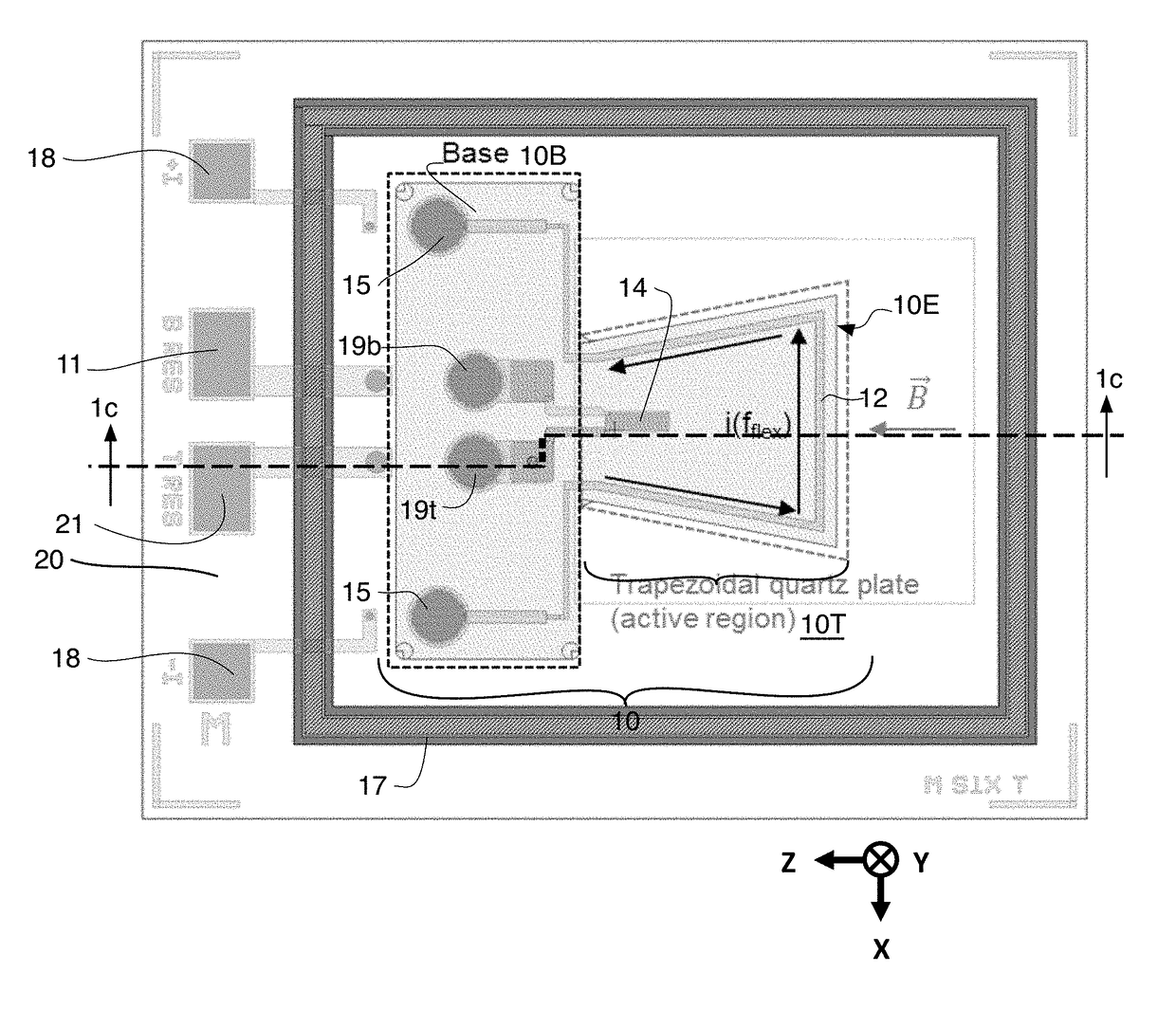
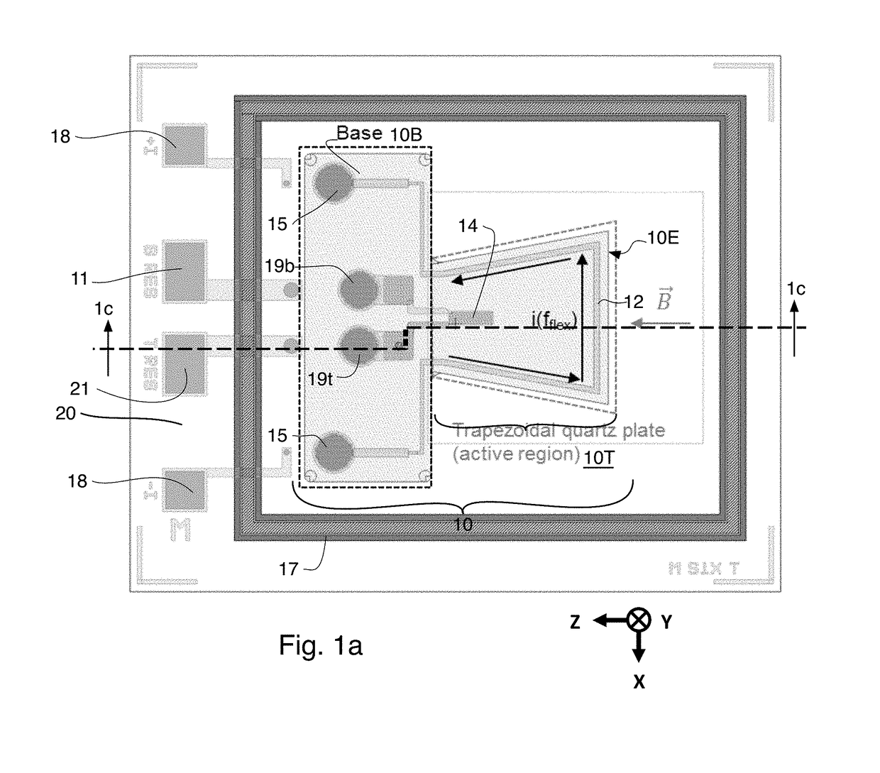
[0037]FIG. 1a is a top or plan view of an embodiment of a quartz magnetometer in accordance with one aspect of the present invention, this embodiment having a quartz plate with a base portion 10B and an integral active region 10T, which, in this embodiment, is formed with a trapezoidal shape (see the dashed outline on the right hand side of this figure). The active region of the quartz plate provides a resonating structure. Unlike a standard rectangular plate where the width of its active portion remains constant along the entire length of the active portion of the plate (along the horizontal axis Z), this singly clamped trapezoidal plate 10T widens along the plate's length starting from its fixed end or base 10B (see the dashed outline on the left hand side of this figure) and reaches a maximum width at the tip or free end of the plate 10E.

[0038]This trapezoidal shape of the embodiment of FIG. 1a allows for a longer current path or loop 12 (current flows around the current loop 12,...


PUM


Abstract

A resonator and/or a magnetometer has a resonating structure which is naturally resonant in at least one resonant mode, the resonating structure being significantly wider at a free end thereof than it is at a fixed end thereof, the resonating structure having at least one pair of sense electrodes disposed on opposing major surfaces of the resonating structure and having a conductive path formed as a loop, the loop being disposed near or at edges of the resonating structure so that the loop follows a path which is significantly wider at the free end of the resonating structure than it is at the fixed end of the resonating structure and wherein the at least one pair of sense electrodes are formed inwardly of the edges of the resonating structure and also inwardly of the path of the loop.

Description

CROSS REFERENCE TO RELATED APPLICATIONS[0001]This Application claims the benefit of U.S. Provisional Patent Application Ser. No. 62 / 104,227 filed 16 Jan. 2015 and entitled “Quartz Micro-Magnetometer with Trapezoidal Quartz Resonant Plate for Enhanced Magnetic Sensitivity” the disclosure of which is hereby incorporated herein by reference.[0002]This Application is related to U.S. Provisional Patent Application Ser. No. 61 / 943,213 filed 21 Feb. 2014 and entitled “A Micro-Scale Piezoelectric Resonating Magnetometer” and to U.S. patent application Ser. No. 14 / 628,182 filed 20 Feb. 2015 and entitled “A Micro-Scale Piezoelectric Resonating Magnetometer”. The disclosure of these two applications are also hereby incorporated herein by reference.[0003]This Application is also related to U.S. patent application Ser. No. 14 / 997,423 filed on the same date as this application and entitled “A Piezoelectric Magnetometer Capable of Sensing a Magnetic Field in Multiple Vectors”, the disclosure of wh...

Claims


Application Information

Patent Timeline
Patent Type & Authority Patents(United States)
IPC IPC(8): G01R33/028H01L41/09H01L41/047
CPCG01R33/0283H01L41/09H01L41/047
Inventor NGUYEN, HUNGSORENSON, LOGAN D.PERAHIA, RAVIVCHANG, DAVID T.ERBLAND, JOSHUA A.
Owner HRL LAB
Why Eureka
Try Eureka