Cooling and heating cup holder

a technology for heating cups and cups, applied in the field of cooling and heating cup holders, can solve the problems of insufficient efficiency of efficient mounting of cup holders in vehicles, insufficient efficiency of providing air conditioning systems, and inefficient structures, so as to maximize heat efficiency and improve heat exchange efficiency

Active Publication Date: 2018-11-20
HYUNDAI MOTOR CO LTD
View PDF27 Cites 2 Cited by
  • Summary
  • Abstract
  • Description
  • Claims
  • Application Information

AI Technical Summary

Benefits of technology

[0010]Various aspects of the present invention are directed to providing a cooling and heating cup holder capable of having configuration disposed to improve a heat exchanging efficiency when a vehicle is cooled and maximizing a heat efficiency when cooling and heating functions are simultaneously performed in a plurality of cup holders.
[0021]The air inlet may be provided with a grille part to prevent an introduction of foreign materials from an outside.

Problems solved by technology

In the case of this cup holder, a thermoelectric element using electrical energy has been used to achieve both cooling and heating effects, but a technology of efficiently mounting the cup holder in the vehicle and efficiently providing an air conditioning system is insufficient.
However, even though the related art is used, it is not an efficient structure when the air conditioning system is efficiently provided, or the cooling and heating functions are simultaneously performed, or one thermoelectric element is used.

Method used


Image

  • Cooling and heating cup holder
  • Cooling and heating cup holder
  • Cooling and heating cup holder

Examples


Embodiment Construction

[0033]Reference will now be made in detail to various embodiments of the present invention(s), examples of which are illustrated in the accompanying drawings and described below. While the invention(s) will be described in conjunction with exemplary embodiments, it will be understood that the present description is not intended to limit the invention(s) to those exemplary embodiments. On the contrary, the invention(s) is / are intended to cover not only the exemplary embodiments, but also various alternatives, modifications, equivalents and other embodiments, which may be included within the spirit and scope of the invention as defined by the appended claims.

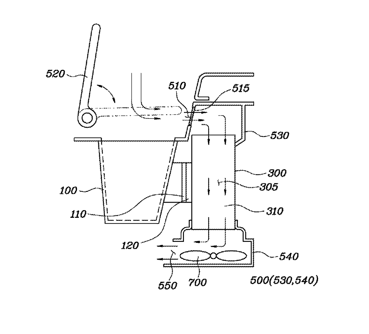
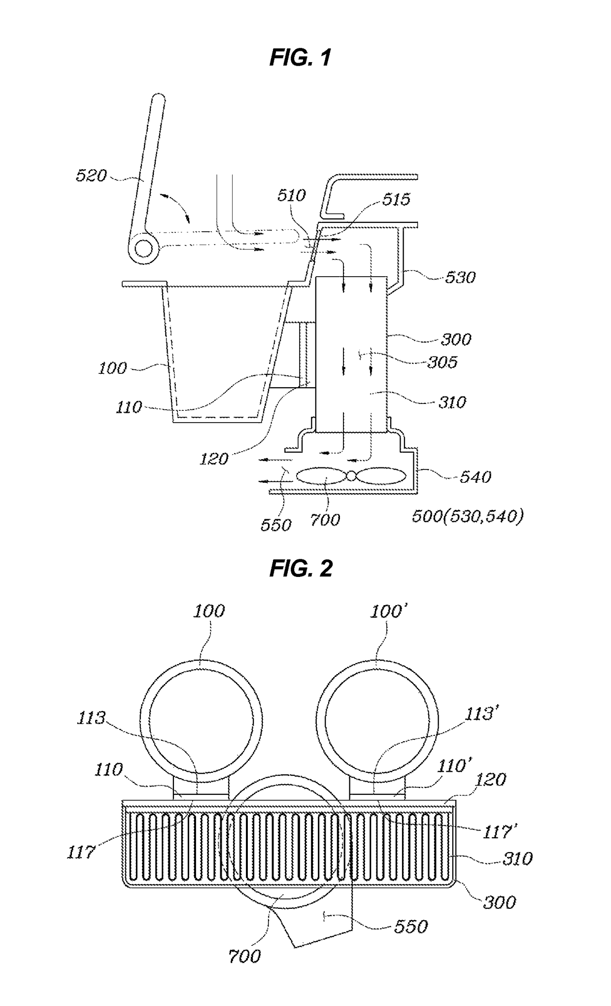
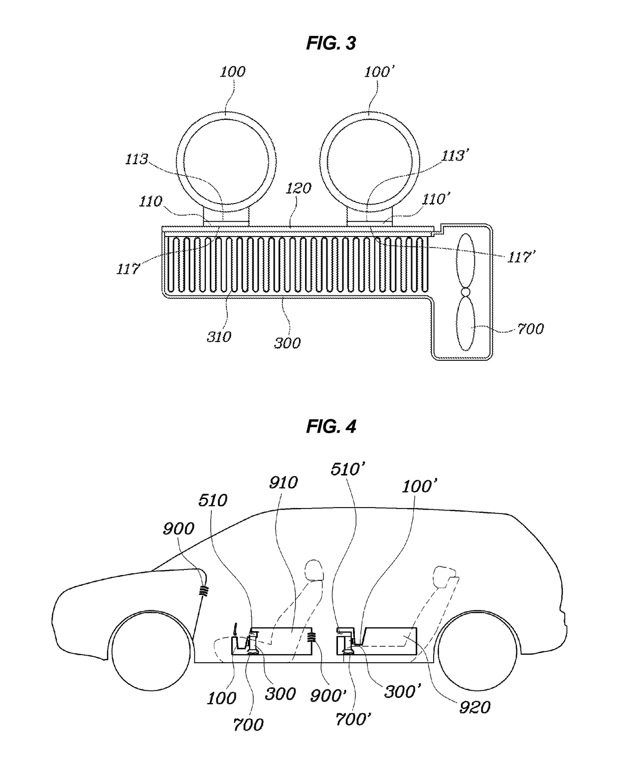
[0034]FIG. 1 is a side view showing a cooling and heating cup holder according to various embodiments of the present invention. FIG. 2 is a plan view showing the cooling and heating cup holder having a blower formed at a lower portion thereof according to various embodiments of the present invention. FIG. 3 is a plan view showing ...


PUM


Abstract

A cooling and heating cup holder may include a plurality of holder bodies having a container shape, a plurality of thermoelectric elements each provided to sides of the plurality of holder bodies, a heat dissipating part installed to be thermally connected to a heat dissipating surface of the plurality of thermoelectric elements, a housing embedding the heat dissipating part and having an air inlet formed at an upper portion thereof, and a blower being embedded in the housing and positioned at an upper portion or a lower portion of the heat dissipating part to allow the air discharged from a bent part and introduced through the air inlet to be heat-exchanged.

Description

CROSS REFERENCE TO RELATED APPLICATION[0001]The present application claims priority to Korean Patent Application No. 10-2014-0072051 filed Jun. 13, 2014, the entire contents of which is incorporated herein for all purposes by this reference.BACKGROUND OF THE INVENTION[0002]Field of the Invention[0003]The present invention relates to a cooling and heating cup holder capable of being mounted in a vehicle, or the like to store a cup and perform cooling and heating functions.[0004]Description of Related Art[0005]A vehicle, or the like, has been provided with various cup holders. This cup holder generally has only a simple holding function. However, in some vehicles, a cup holder having cooling and heating functions has been introduced. In the case of this cup holder, a thermoelectric element using electrical energy has been used to achieve both cooling and heating effects, but a technology of efficiently mounting the cup holder in the vehicle and efficiently providing an air conditionin...

Claims


Application Information

Patent Timeline
Patent Type & Authority Patents(United States)
IPC IPC(8): F25B21/04B60N3/10B60N2/75
CPCB60N3/104F25B21/04B60H1/00271F25B21/02F25B2321/021B60N3/101
Inventor OH, MAN JUKIM, JAE WOONGPARK, JAE WOO
Owner HYUNDAI MOTOR CO LTD
Why Eureka
Try Eureka