Multi-functional battery box

a battery box and multi-functional technology, applied in the field of multi-functional battery boxes, can solve the problems of shortening the life of the entire battery box, causing great inconvenience to users, etc., and achieve the effect of convenient use and longer li

Active Publication Date: 2018-11-20
ACE GIFT&CRAFTNINGBOCO LTD
View PDF7 Cites 5 Cited by
  • Summary
  • Abstract
  • Description
  • Claims
  • Application Information

AI Technical Summary

Benefits of technology

[0033]The present invention has the following beneficial effects compared with the prior art:
[0034]1. The power supply of the printed circuit board is realized by two different control ways, i.e. the spring piece and the electro-acoustic transducer, in the present invention, so the battery box has two different switching modes. Provision of the change-over switch allows switching between the two switching modes, making the battery box easier and more flexible to use.
[0035]2. Two switching modes can be readily switched, reducing the loss to the switch in any mode, protecting the battery box against damages due to continuous use of one switching mode, and effectively prolonging the life of the battery box.
[0036]3. The consumption of the electricity of the power source is effectively reduced by control of the power supply of the printed circuit board through the electro-acoustic transducer, prolonging the service hours of the power source.

Problems solved by technology

The battery box is of a simple structure, easy to use and assemble, but it has the following technical disadvantages: 1. the printed circuit board of the battery box can be energized by pressing the spring piece only and it is not easy to turn on and off the battery box, causing great inconvenience to users; 2. such mechanical switching method can cause damage to the spring piece, poor contact between the contact and the battery and other problems, resulting in that the printed circuit board cannot supply power as expected and the battery box cannot function, shortening the entire battery box's life.

Method used


Image

  • Multi-functional battery box
  • Multi-functional battery box
  • Multi-functional battery box

Examples


Embodiment Construction

[0050]The technical solution of the present invention will be further described hereinafter with the accompanying figures and embodiments, but the present invention is not limited to these embodiments.

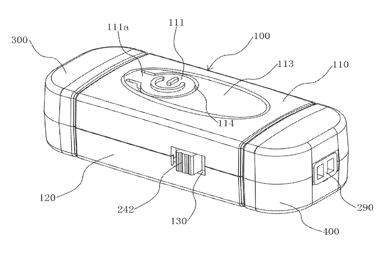
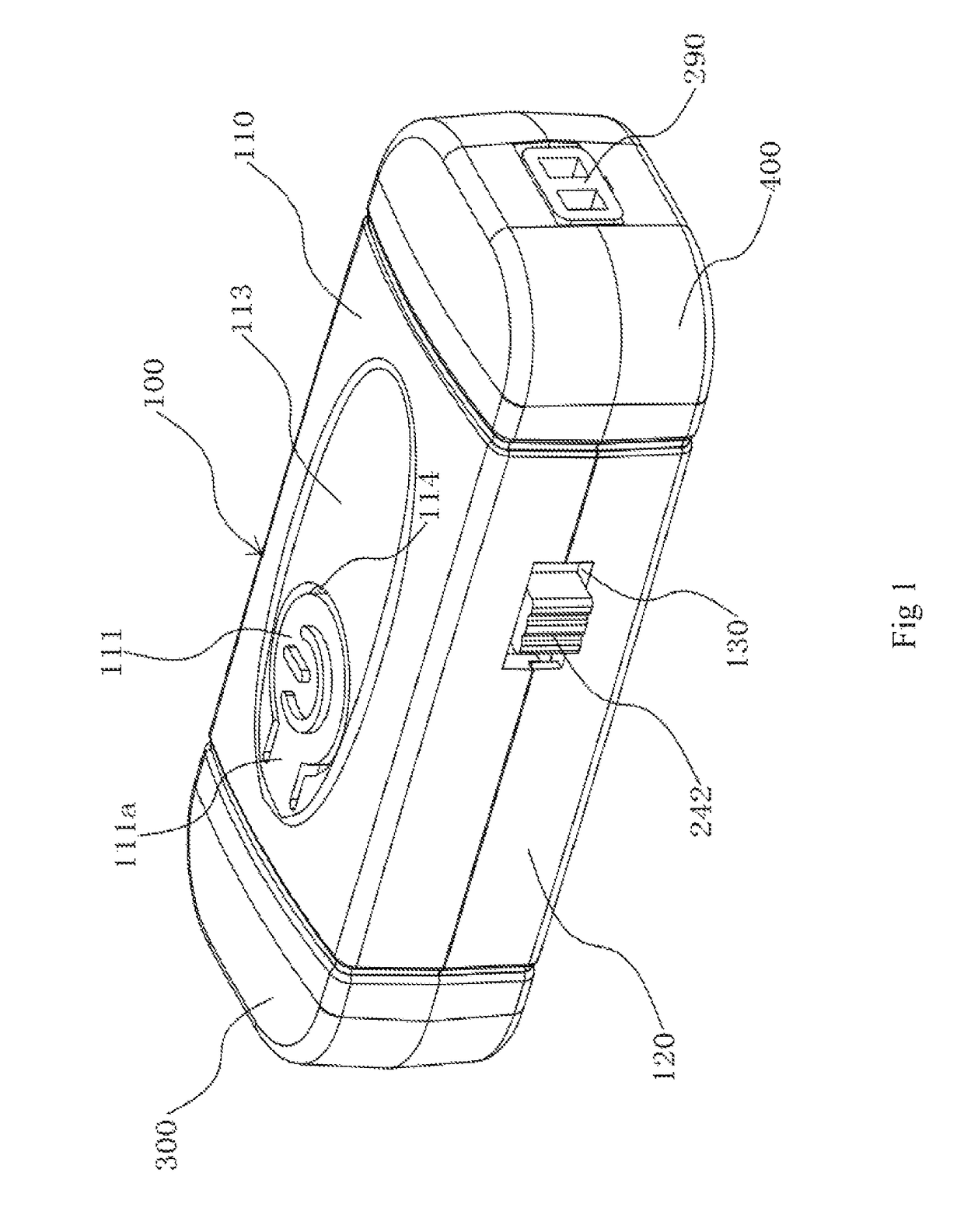
[0051]As shown in FIG. 1-4, the multi-functional battery box of the present invention comprises a case 100 and a printed circuit board 200 accommodated in the case 100.

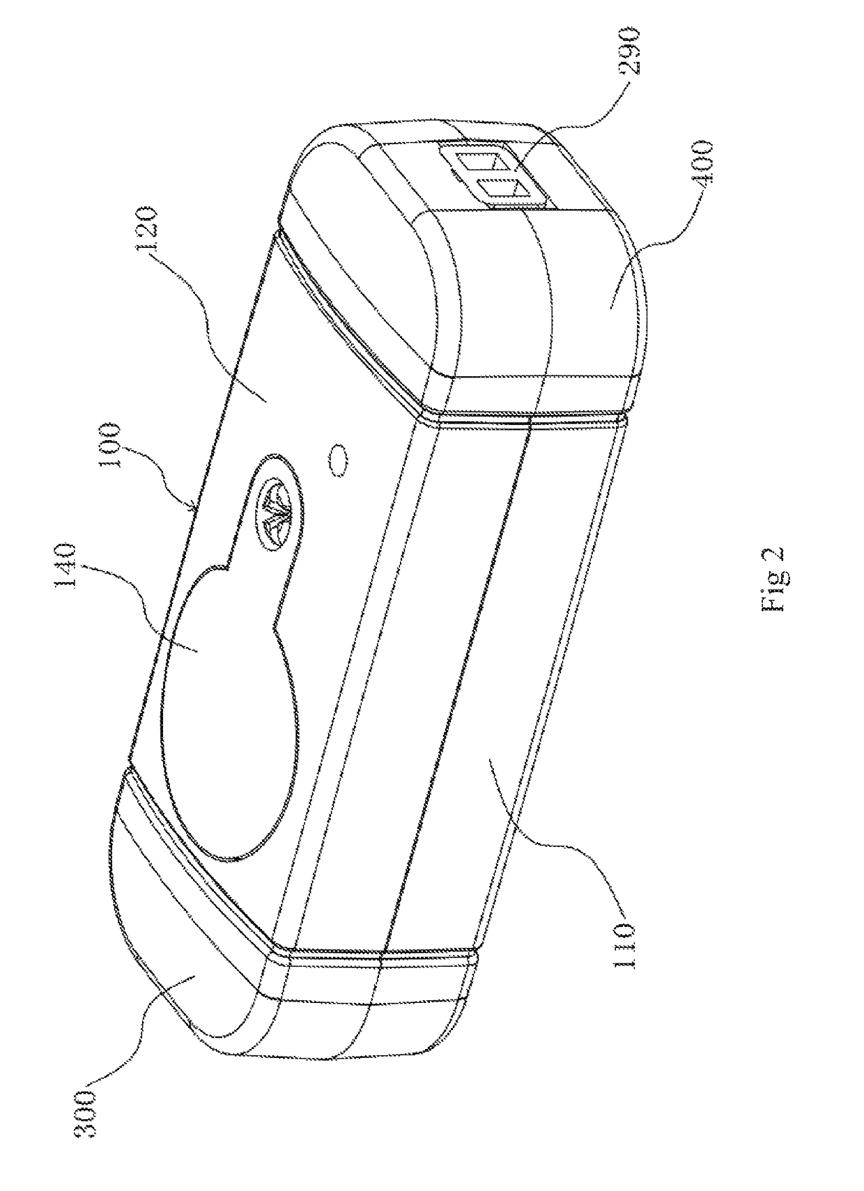
[0052]The case 100 may be square, round, elliptic or other shapes, and the case 100 comprises an upper case body 110 and a lower case body 120 which can be removably assembled to form an accommodating cavity by bringing them to face each other. As shown in FIG. 1, FIG. 3 and FIG. 5, a spring piece 111 is arranged on the upper case body 110 and can move relative to the same, and a protruding post 112 is arranged on and protruding from the inner surface of the spring piece 111.

[0053]As shown in FIG. 2, FIG. 4 and FIG. 7, the printed circuit board 200 is horizontally arranged in the accommodating cavity and connected with t...


PUM

PropertyMeasurementUnit
poweraaaaaaaaaa
conductiveaaaaaaaaaa
flexibleaaaaaaaaaa

Abstract

The present invention discloses a multi-functional battery box, belonging to the field of power supply devices; a multi-functional battery box, comprising: a case, having an accommodating cavity; a printed circuit board, located in the accommodating cavity and permanently connected with the case; a power source, located in the accommodating cavity and in contact with the printed circuit board; an electro-acoustic transducer, permanently arranged on the printed circuit board and electrically connected with the printed circuit board; a spring piece, arranged on the case and in contact with the printed circuit board; a change-over switch, flexibly connected with the printed circuit board; the present invention has two switching modes that can be flexibly switched, making the battery box easier and more flexible to use, reducing the loss to the switch and prolonging the life of the battery box.

Description

CROSS-REFERENCE TO RELATED APPLICATIONS[0001]This application claims priority to Chinese Patent Application No. 201610793042.4 filed on Aug. 31, 2016, the entire contents of which are incorporated by reference herein.BACKGROUND OF THE INVENTION1. Technical Field[0002]The present invention relates to the field of power supply devices, and more particularly, to a multi-functional battery box.2. Description of Related Art[0003]The battery box is a common structure for supplying power. It is most often found that a connecting latch is connected to the ends of accessories. As the life improves, a battery box can be used as a connecting latch to supply power for the illuminating accessories in the prior art.[0004]For instance, the authorized publication No. CN 204792984 U utility model discloses a battery box and the necklace with thereof. The battery box comprises a case and a printed circuit board accommodated in the case, wherein the printed circuit board is provided with a contact, a ...

Claims


Application Information

Patent Timeline
Patent Type & Authority Patents(United States)
IPC IPC(8): H01M2/10A44C15/00H01M6/50H01M50/202H01M50/244H01M50/247H01M50/271H01M50/284H01M50/569
CPCH01M2/1022A44C15/005A44C15/0015H01M2/1016H01M2/1055H01M2/1066H01M6/50H01M6/5005H01M2/1044H01M2220/30H01M10/4257H01M2010/4271H01M50/202H01M50/271H01M50/284H01M50/244H01M50/569H01M10/425Y02E60/10H01M50/213H01M50/216
Inventor QIN, YANBEI
Owner ACE GIFT&CRAFTNINGBOCO LTD
Why Eureka
Try Eureka