
Successive approximation register analog-digital converter having a split-capacitor based digital-analog converter

a digital analog and approximation register technology, applied in analogue/digital/analogue conversion, analogue/digital conversion, instruments, etc., can solve the problems of increasing the settling time and power consumption of the dac, limiting the effective number of bits, and scaling power consumption

Active Publication Date: 2018-11-20
SK HYNIX INC
View PDF10 Cites 4 Cited by
  • Summary
  • Abstract
  • Description
  • Claims
  • Application Information

AI Technical Summary

Benefits of technology

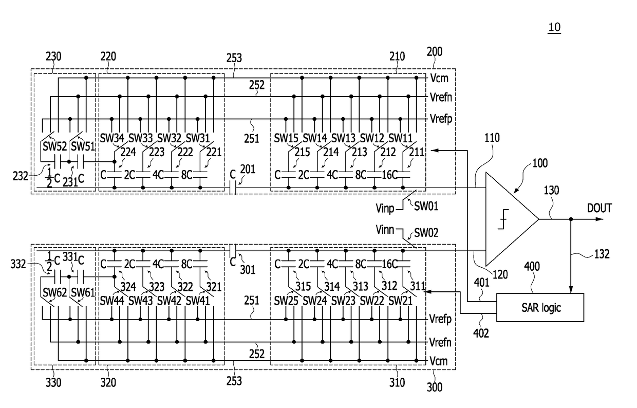
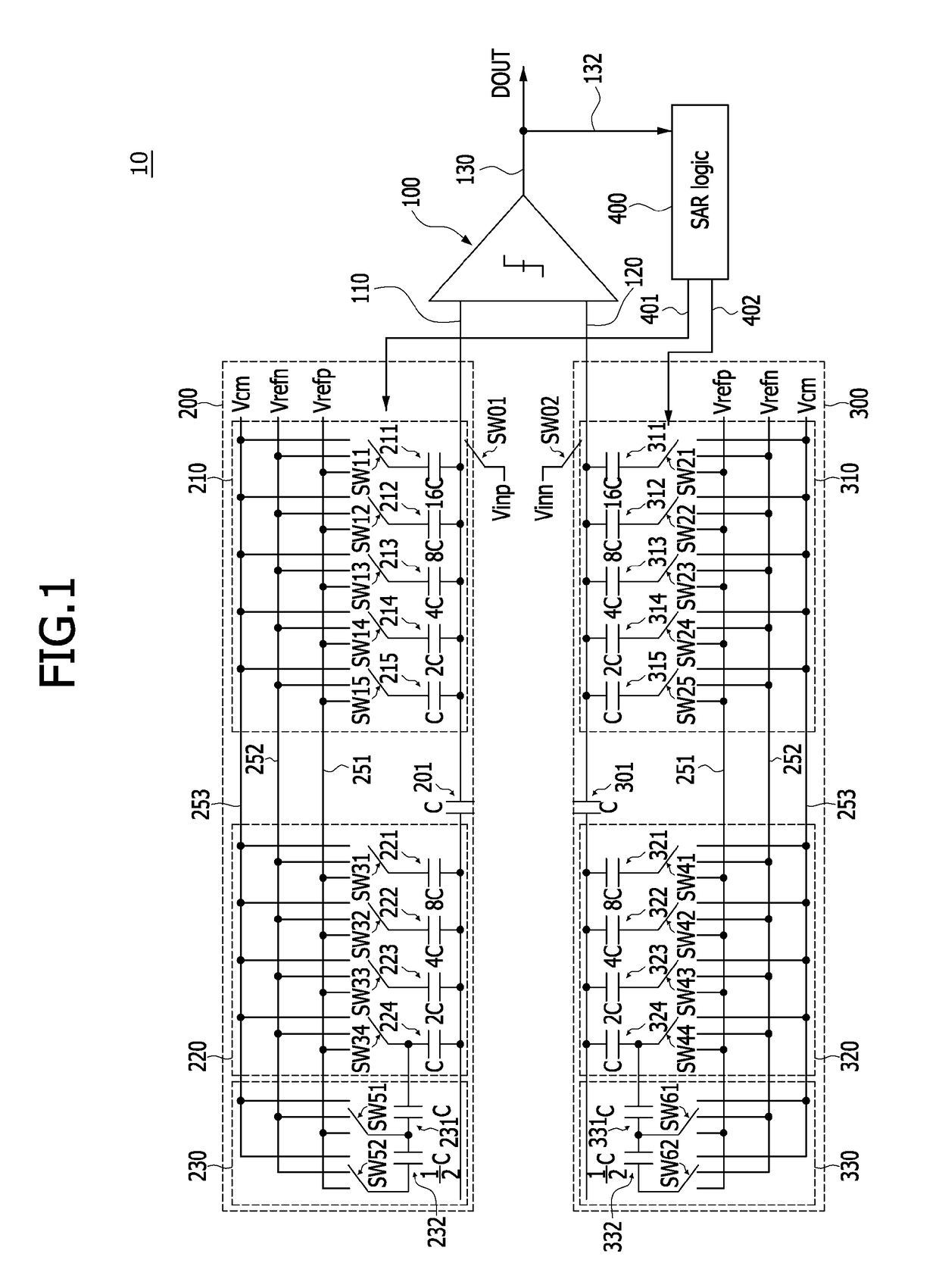
The patent describes a type of analog-to-digital converter that uses a successive approximation register (SAR) logic. The converter has three stages of capacitors that generate input signals for a comparator. These stages are called "positive" and "negative" stages, and each includes a first and second stage. The first stage generates input signals for the comparator's most significant bits (MSBs), the second stage generates input signals for intermediate bits, and the third stage generates input signals for the least significant bits (LSBs) and the bits that are neighbors to the LSBs. The technical effect of this design is that it allows for accurate and efficient analog-to-digital conversion with a simple and compact circuit design.

Problems solved by technology

Also, most of the SAR ADC consume dynamic power, which has a great effect on scaling power consumption according to frequency.
On the other hand, due to the high total capacitance, the DAC occupies a large area, which results in an increase in the settling time and power consumption of the DAC, which is disadvantageous for high-speed operation.
However, this scheme shows a limitation in increasing the effective number of bits (hereinafter referred to as “ENOB”) that can be implemented by the SAR ADC to more than a certain number of bits.

Method used


Image

  • Successive approximation register analog-digital converter having a split-capacitor based digital-analog converter
  • Successive approximation register analog-digital converter having a split-capacitor based digital-analog converter
  • Successive approximation register analog-digital converter having a split-capacitor based digital-analog converter

Examples


Embodiment Construction

[0011]In the following description of the embodiments, it will be understood that the terms “first” and “second” are intended to identify an element, but not used to define only the element itself or to mean a particular sequence. In addition, when an element is referred to as being located “on”, “over”, “above”, “under” or “beneath” another element, it is intended to mean relative position relationship, but not used to limit certain cases that the element directly contacts the other element, or at least one intervening element is present therebetween. Further, when an element is referred to as being “connected” or “coupled” to another element, the element may be electrically or mechanically connected or coupled to the other element directly, or may form a connection relationship or coupling relationship by replacing the other element therebetween.

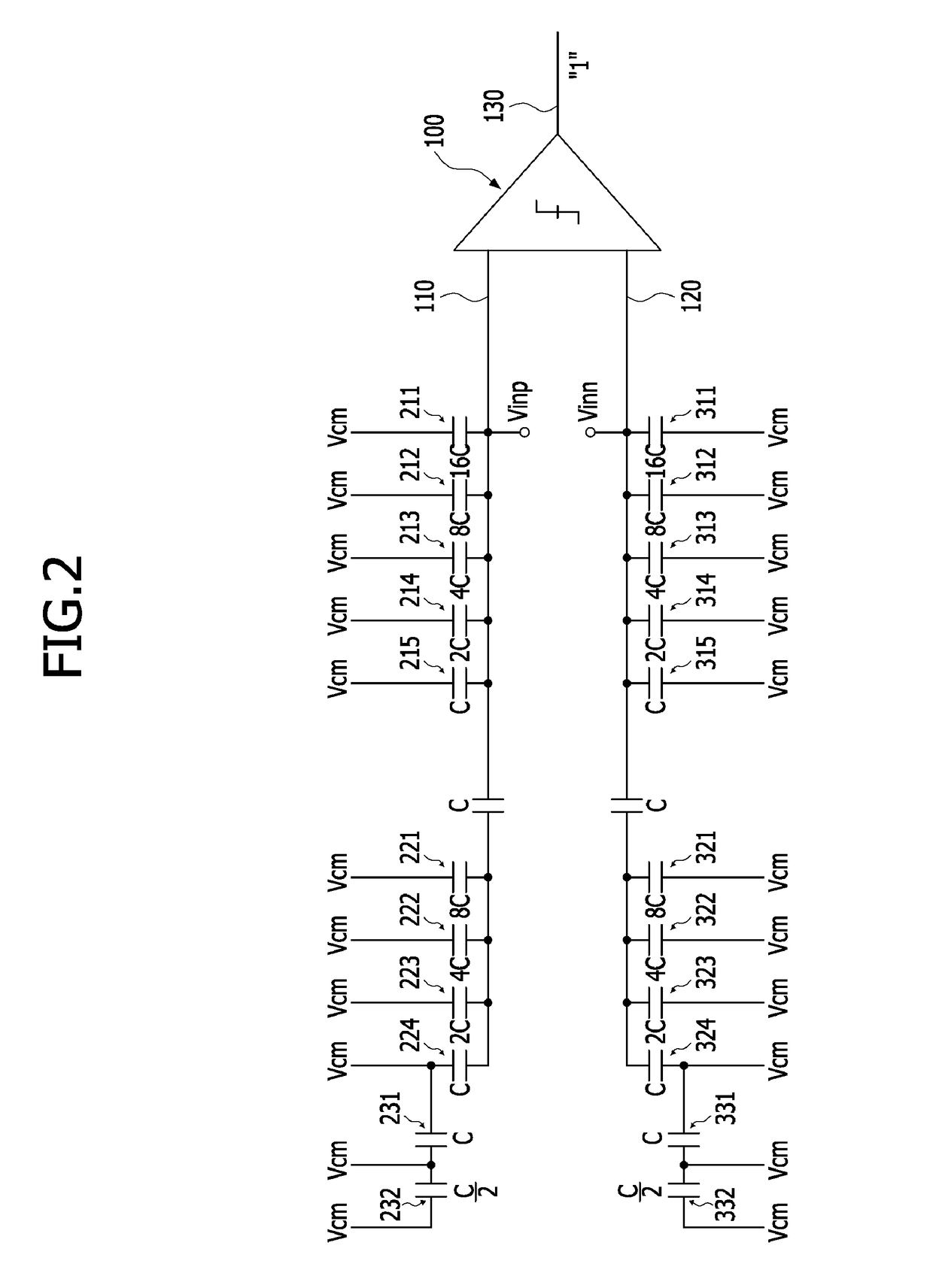
[0012]FIG. 1 is a circuit diagram illustrating an example of an SAR ADC 10 including a split-capacitor based DAC according to an embodime...


PUM


Abstract

A successive approximation register analog-digital converter including a split-capacitor based digital-analog converter includes a comparator, a split-capacitor based digital-analog converter including a positive capacitor array and a negative capacitor array, and a successive approximation register logic. The positive capacitor array and the negative capacitor array each includes a positive capacitor array of a first stage and a negative capacitor array of a first stage that generate input signals of the comparator corresponding to upper bits including an MSB, respectively, a positive capacitor array of a second stage and a negative capacitor array of a second stage that generate input signals corresponding to intermediate bits, and a positive capacitor array of a third stage and a negative capacitor array of a third stage that generate input signals corresponding to lower bits of an LSB and a next to bit of the LSB.

Description

CROSS-REFERENCE TO RELATED APPLICATION[0001]The present application claims priority under 35 U.S.C 119(a) to Korean Patent Application No. 10-2017-0032078, filed on Mar. 14, 2017, which is herein incorporated by reference in its entirety.BACKGROUND1. Technical Field[0002]Various embodiments of the present disclosure generally relate to a successive approximation register analog-digital converter and, more particularly, to a successive approximation register analog-digital converter having a split-capacitor based digital-analog converter.2. Related Art[0003]Recently, a demand for lower power consumption and a smaller area in the implementation of a system on chip (SoC) has increased. In order to meet such a demand, a successive approximation register (hereinafter referred to as “SAR”) structure is mainly used in designing an analog-digital converter (hereinafter referred to as “ADC”) for converting an analog value to a digital value. SAR ADC is typically composed of a comparator, a d...

Claims


Application Information

Patent Timeline
Patent Type & Authority Patents(United States)
IPC IPC(8): H03M1/12H03M1/46
CPCH03M1/466H03M1/001H03M1/38H03M1/0682H03M1/462H03M1/468H03M1/804H03M1/1245
Inventor CHANG, KEUNJIN
Owner SK HYNIX INC
Learn More