Lighting apparatus with adjustable irradiance

a technology of light emitting apparatus and irradiance, which is applied in the direction of electrical apparatus, instruments, image data processing, etc., can solve the problems of inability to completely eliminate the fluctuation of radiant power, the irradiance emitted is sensitively adjusted, and the radiant power is subject to significant fluctuations

Active Publication Date: 2018-11-20
B&R IND AUTOMATION GMBH
View PDF11 Cites 2 Cited by
  • Summary
  • Abstract
  • Description
  • Claims
  • Application Information

AI Technical Summary

Benefits of technology

[0015]It is advantageous to measure the intensity of the reflected component at the edge of the optical covering. Among other things, this offers the advantage that the measurement occurs in a region that is less sensitive to contamination (and thus to an influence on the measurement). Moreover, the formation of shadows is prevented in this way, or the area that is to be illuminated is not deprived of light by sensors placed between the light source and the illumination area.
[0016]A plurality of light sensors, preferably four, can be provided at the edge of the optical covering, each of which detects the intensity of the reflected component at multiple, preferably four, locations on the edge. This can be helpful when the optical covering is rectangular in shape, but also at four locations on a round or oval optical covering. Measuring the intensity of the reflected component with multiple light sensors permits the transmitted radiant power to be detected as a function of the location on the optical covering, which is particularly advantageous. In this way, the transmitted radiant power at multiple locations on the optical covering can be calculated from different values of the intensity at different points on the edge of (or within) the optical covering by a suitable mathematical model. This then permits conclusions to be drawn about the locally dependent irradiance at defined working distances in the illumination area.
[0017]The light sensor or sensors measure the reflected component in the optical covering and can thus also be applied directly to the edge or edges of the optical covering. This represents a particularly simple configuration; alternatively, the reflected component could also be conveyed by an optical waveguide, for example, and could be evaluated by the light sensor or sensors. Doing so could reduce the further formation of shadows, for instance, wherein the sensors at the edge of the optical cover do not exert a significant influence on the arrangement. Of course, conveying the reflected component in this way is associated with additional expenses. It is also possible that the intensity of the reflected component emerging at the edge can be measured at a particular distance from the edge without optical waveguides.
[0031]Illuminations, particularly with LEDs, are often used in flash mode in the field of machine vision, since continuous illumination is not needed for many applications. The reasons can be as follows. An LED is capable of momentarily coping with up to five times the nominal current. This makes it possible to emit significantly greater radiant power for a short time. Additionally, the flash mode increases service life and lowers the temperature within the device compared to continuous operation. Even if ambient light is always a source of disturbance in the field of machine vision applications and its influence should be reduced or fully eliminated by suitable measures whenever possible, doing so can influence the measurement of radiant power. For instance, the time before the light source is activated in flash mode can be used to measure reflections of the ambient light. In this way, the effects of the ambient light on the measuring accuracy can be significantly reduced.

Problems solved by technology

Unfortunately, LEDs are subject to significant fluctuations in emitted radiant power.
However, other light sources can also suffer from similar problems.
In practice, this problem leads to the fact, for instance, that lighting apparatus (e.g. LEDs) in machine vision applications are often switched on for a longer period of time before an evaluation is started so as to minimize a fluctuation in radiant power that occurs in the first 15-30 minutes as a result of the increase in self-heating.
This fluctuation in the radiant power cannot be entirely eliminated, though, since the emitted radiant power depends upon many other factors, such as the heating of the lighting apparatus or light source or the ambient temperature, the hours of operation, etc.
However, the arrangement shown in DE 1 755 074 B1 is entirely unsuitable for machine vision applications, since this application depends upon as much light as possible being emitted by the lighting apparatus, and a total reflectance in an optical covering of the lighting apparatus would thus be completely counterproductive.

Method used


Image

  • Lighting apparatus with adjustable irradiance
  • Lighting apparatus with adjustable irradiance
  • Lighting apparatus with adjustable irradiance

Examples


Embodiment Construction

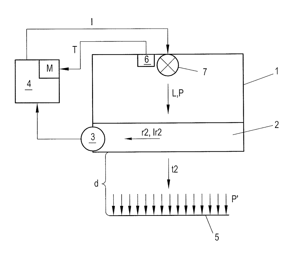
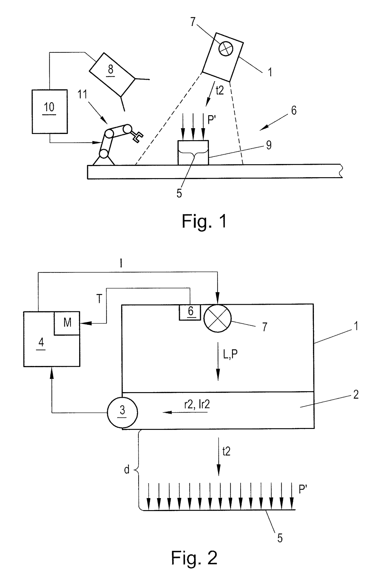
[0012]The problem addressed by the present invention is that of indicating a lighting apparatus for a machine vision application which permits a precise adjustment of the irradiance emitted by the lighting apparatus in an illuminated area as a function of the working distance.

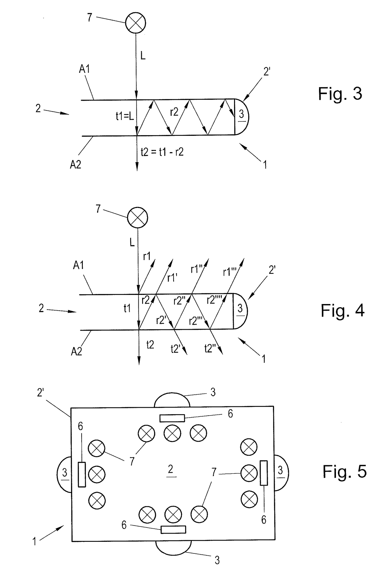
[0013]This problem is solved in that a transmitted component of a light which is emitted by a light source and which insides onto an optical covering in the lighting apparatus is transmitted through the optical covering, and a reflected component of the incident light is reflected in the optical covering. The intensity of the reflected component in the optical covering is detected by a light sensor. Furthermore, it is possible to implement an arrangement of the lighting apparatus and a control unit, wherein the control unit is connected to the light sensor and the light source, and it is configured such that, based on the intensity of the reflected component, the radiant power of the light source can be regulat...


PUM


Abstract

To indicate a lighting means for a machine vision application where the resulting irradiance (P′) in an illuminated area (5) at a working distance (d) can be precisely adjusted, an optical covering (2) of the lighting means (1) is provided, which is configured such that a transmitted part (t2) of the incident light (L) passes through (1) the optical covering (2), and a reflected component (r2) of the incident light (L) is reflected in the optical covering (2), wherein a light sensor (3) is provided that detects the intensity (Ir2) of the reflected component (r2) in the optical covering (2). Furthermore, a method is indicated, according to which the intensity (Ir2) of the reflected component (r2) is detected and the radiant power (P) of the light source (1) is regulated on the basis of the intensity (Ir2) in order to adjust the irradiance (P′) of the transmitted component (t2).

Description

CROSS-REFERENCE TO RELATED APPLICATIONS[0001]The present application claims priority under 35 U.S.C. § 119(a) of Austrian Patent Application No. A50435 / 2016 filed May 11, 2016, the disclosure of which is expressly incorporated by reference herein in its entirety.BACKGROUND OF THE INVENTION1. Field of the Invention[0002]The present invention relates to a lighting apparatus and to a method for providing illumination in a machine vision application, having a light source that emits light with a radiant power, and to the use of said lighting apparatus.2. Discussion of Background Information[0003]In industrial illumination, especially in so-called machine vision applications, LEDs are gradually becoming the state of the art and are meanwhile replacing other types of lighting apparatus, including with respect to radiant power. As is known, machine vision refers to methods for controlling and / or regulating technical processes, such as machines or systems, wherein the information required t...

Claims


Application Information

Patent Timeline
Patent Type & Authority Patents(United States)
IPC IPC(8): H05B37/02H05B33/08G06T7/00H05B44/00
CPCH05B33/0851H05B33/0854H05B37/02G06T2207/10152G06T7/0004G05D25/00H05B45/00H05B47/10H05B45/18H05B45/12
Inventor HUBER, MATTHIAS
Owner B&R IND AUTOMATION GMBH
Why Eureka
Try Eureka