Supercharge air cooler

a technology of air cooler and supercharger, which is applied in the direction of combustion-air/fuel-air treatment, machines/engines, lighting and heating apparatus, etc., can solve the problem that the temperature remains too high to achieve the performance desired today

Inactive Publication Date: 2018-12-04
MAHLE INT GMBH
View PDF12 Cites 1 Cited by
  • Summary
  • Abstract
  • Description
  • Claims
  • Application Information

AI Technical Summary

Benefits of technology

[0005]The present invention is a charge air cooler of which the thermal and dimensional performances greatly exceed those of the prior-art charge air coolers by proposing a simple and economical solution.
[0007]Each pair of plates forms between its plates a second flat flow tube in which a second fluid circulates between a second inlet orifice and a second outlet orifice. The two flat tubes are coplanar and form parallel arms extending in a longitudinal direction of the common plane, which direction is itself perpendicular to a transverse direction of the same common plane in which a transverse air flow traverses the heat exchanger, passing between the pairs of plates. The first tube is upstream in the air flow and the second tube is downstream of the air flow. The air flow is therefore first in thermal exchange with the first tube, then in thermal exchange with the second tube. Thus, the heat exchanger has the advantage of combining two successive heat exchange circuits in one simple structure, which makes it possible to optimise exchange with the traversing air flow.
[0011]It is advantageous for the thermal efficiency of the exchanger that the inlet orifice of a flat tube is arranged on the downstream arm and the outlet orifice is arranged on the upstream arm.
[0020]In another specific embodiment of the heat exchanger, the two flat tubes each having two parallel longitudinal arms connected at their two ends together forming a 00, the inlet and outlet orifices are arranged in the middle of the longitudinal arms. This central arrangement is of interest in two ways. Firstly, the exchanger must be arranged and connected in a structure, and some of them have the fluid inlet-outlet connections placed at the centre of the exchanger. An exchanger of which the inlets-outlets are at the ends of the plates should then be provided with connectors which go from the centre to the end in order thus to connect the structure to the exchanger. These connecting pipes take up significant space, and an exchanger of which the inlets-outlets are at the centre of the plates may be connected directly, and therefore save on the connectors and hence the space necessary for the latter. This space can then be used to increase the number of plates and the heat exchange volume. Secondly, a second advantage of the central connections is that the fluid flow is divided in two, which reduces pressure losses. This improves the flow rate in the cooling system.
[0022]Moreover, the flat tubes in which the fluids circulate are provided with flow disruptors designed to improve thermal exchanges, which disruptors are further apart from each other in the proximity of the inlet orifice than they are in the proximity of the outlet orifice. More particularly, the density of flow disruptors along the flat tubes increases regularly between the inlet orifice and the outlet orifice.

Problems solved by technology

This temperature proves still too high to attain the performances desired nowadays.

Method used


Image

  • Supercharge air cooler
  • Supercharge air cooler
  • Supercharge air cooler

Examples


first embodiment

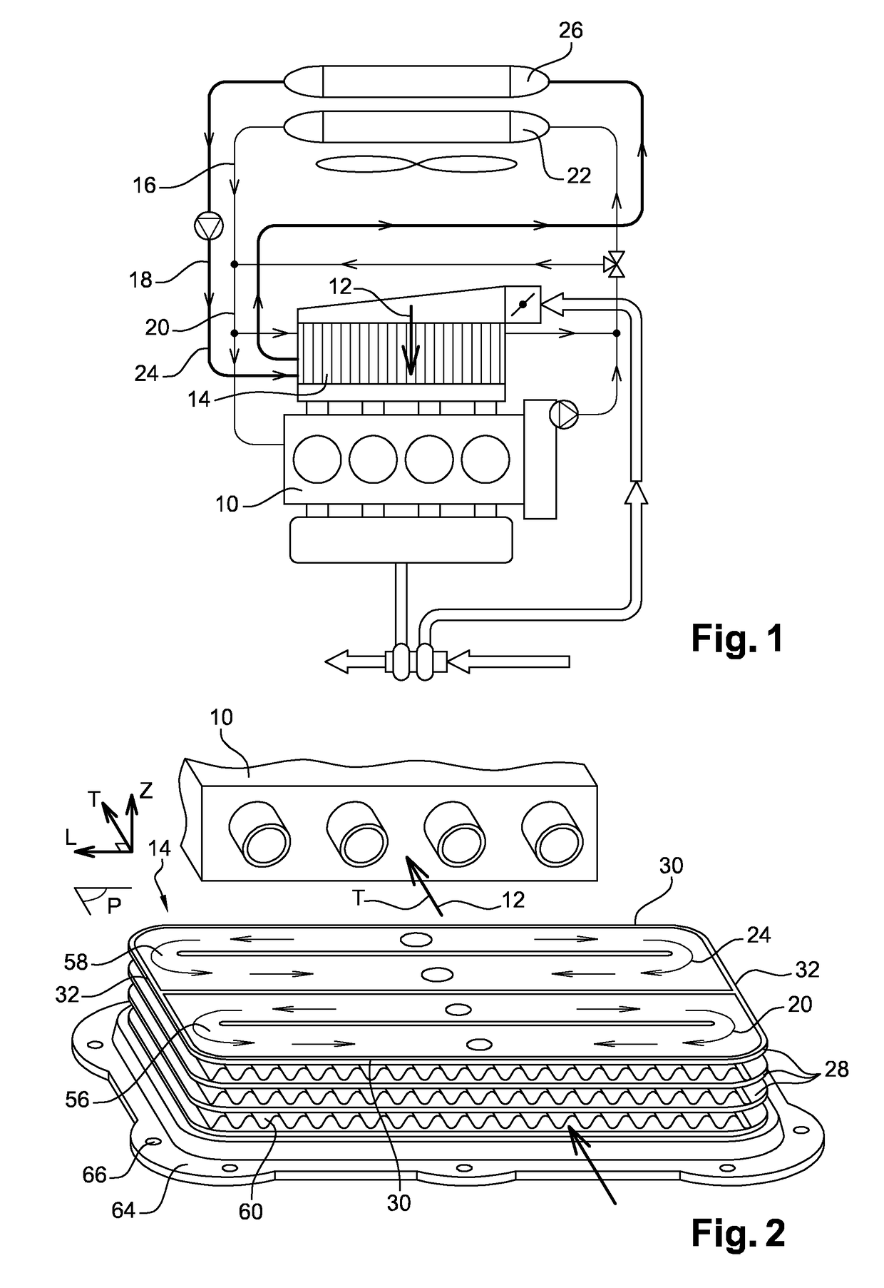
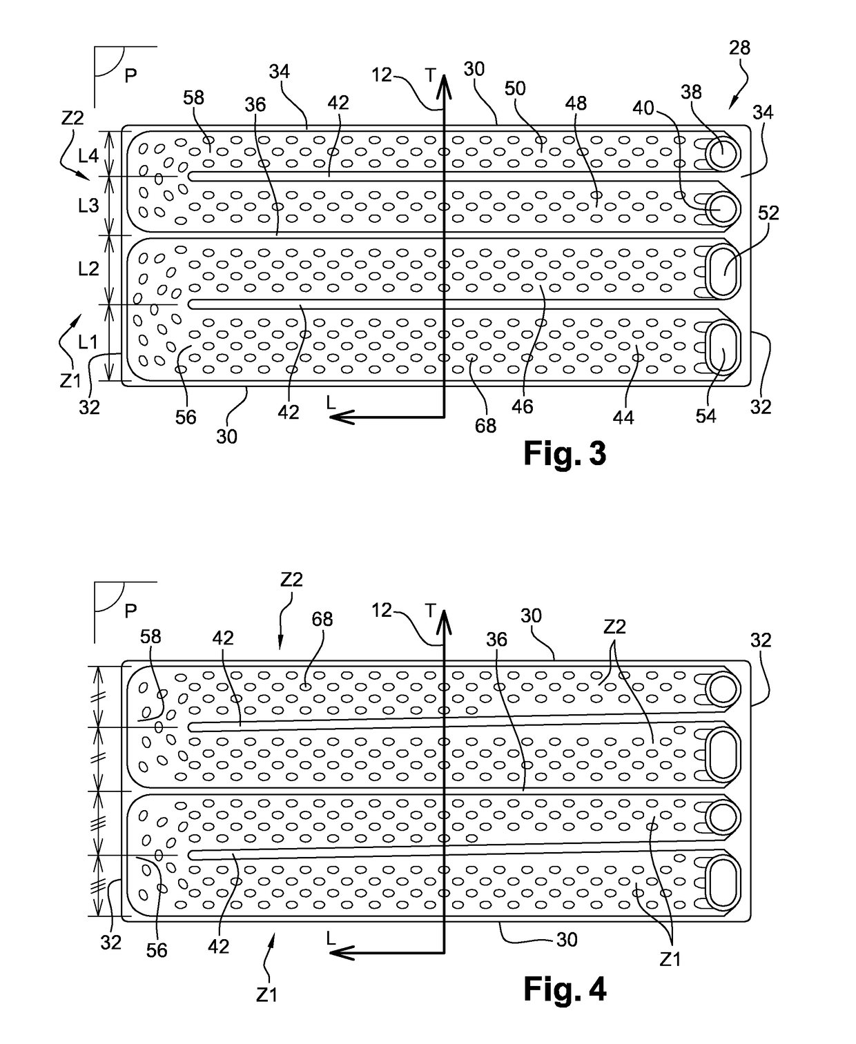
[0050]FIG. 3 shows the metal plates 28 of the charge air cooler 14. The plate 28, shown in a top view, is divided in two by the longitudinal boundary 36 extending along the longitudinal axis L of a transverse edge 32 to the opposite edge 32. In relation to the charge air flow 12 flowing along the transverse axis T, and in the direction of orientation of the latter, the zones Z1, Z2 are marked as the upstream zone Z1 and the downstream zone Z2.

[0051]The upstream zone Z1 is itself provided with a longitudinal barrier 42 partially separating it into two parallel longitudinal arms 44, 46 connected by only one of their ends. The two arms form an upstream arm 44 and a downstream arm 46. The fluid inlet orifice 52 is arranged at the end of the downstream arm 46 while the outlet orifice 54 is arranged at the end of the upstream arm 44. The downstream arm 46, of width L2, by which the fluid 20 enters cold, is less wide than the upstream arm 44, of width L1, by which the same fluid 20 leaves ...

second embodiment

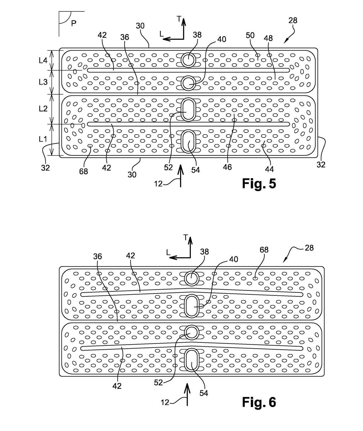
[0068]As above, in this second embodiment shown by FIG. 5, the downstream arm 46, of width L2, by which the fluid 20 enters cold, is less wide than the upstream arm 44, of width L1, by which the same fluid 20 leaves heated, and the downstream arm 50, of width L4, by which the fluid 24 enters cold, is less wide than the upstream arm 48, of width L3, by which the same fluid 24 leaves heated.

[0069]In FIG. 5, the longitudinal barriers 42 extend strictly in the longitudinal direction L, each longitudinal arm therefore having a constant width. FIG. 6 shows an alternative of this second embodiment, in which alternative the barriers 42 form a broken line having two segments which are inclined slightly relative to the strict longitudinal direction L. Each longitudinal arm then has a section which progresses continuously from an inlet orifice to the outlet orifice. At the ends of the arms, where the downstream and upstream meet, the arms have substantially the same width.

[0070]According to FI...


PUM


Abstract

The invention relates to a plate heat exchanger forming between its plates a first flat flow tube in which a first fluid circulates between a first inlet orifice and a first outlet orifice, and a second flat flow tube in which a second fluid circulates between a second inlet orifice and a second outlet orifice. The two flat tubes form parallel arms which extend in a longitudinal direction (L) perpendicular to a transverse air flow traversing the heat exchanger, the first tube being upstream in the air flow and the second tube being downstream.

Description

CROSS-REFERENCE TO RELATED APPLICATION[0001]This application claims the benefit of PCT Application Serial No. PCT / EP2013 / 064812 for a SUPERCHARGE AIR COOLER filed on 12 Jul. 2013, which claims priority to French Application Serial No. FR 1256817 filed on 12 Jul. 2012. Both above PCT Application No. PCT / EP2013 / 064812 and French Application No. FR 1256817 are hereby incorporated by reference in their entirety.TECHNICAL FIELD[0002]The present invention relates to a charge air cooler of an internal combustion engine.TECHNOLOGICAL BACKGROUND OF THE INVENTION[0003]In a vehicle equipped with a turbocharged engine, the charge air is compressed before being injected. Compression generates significant heating to more than 200° C. and so, just upstream of the engine, the air flow traverses a charge air cooler so that the air temperature is lowered to less than 80° C.[0004]This temperature proves still too high to attain the performances desired nowadays. Also, charge air coolers must be as sma...

Claims


Application Information

Patent Timeline
Patent Type & Authority Patents(United States)
IPC IPC(8): F28D7/02F28D9/00F28F3/04F02B29/04F02M35/10F28F13/08F02M35/112F28D21/00
CPCF02B29/0462F02B29/0443F02B29/0475F02M35/10268F02M35/112F28D9/0056F28D9/0093F28F3/044F28F13/08F28D9/0043Y02T10/146F28D2021/0082Y02T10/12
Inventor BERGER, THIERRYAYAD, FADILPROCHETTE, BRUNO
Owner MAHLE INT GMBH
Why Eureka
Try Eureka