
Rotor structure of wound rotor driving motor

a driving motor and rotor cooling technology, which is applied in the direction of windings, magnetic circuit rotating parts, magnetic circuit shapes/forms/construction, etc., can solve the problems of excessive volume and weight of the volume of the volume of the volume, the need for large volume and weight, and the rare earth (nd, dy) metal component of such a permanent magnet is limitedly buried, so as to achieve efficient discharge and reduce the loss of copper resistance of the rotor coil 1. ,

Active Publication Date: 2018-12-04
HYUNDAI MOTOR CO LTD
View PDF21 Cites 3 Cited by
  • Summary
  • Abstract
  • Description
  • Claims
  • Application Information

AI Technical Summary

Benefits of technology

The present invention is a rotor design for a wound rotor driving motor used in electric vehicles. It has an open structure that allows external air to cool the rotor coil and reduces copper loss, increasing motor efficiency and reducing energy consumption. The design eliminates the need for a separate end coil cover and simplifies the assembly process, reducing production costs. Overall, it improves motor durability and reduces the number of components.

Problems solved by technology

However, a rare earth (Nd, Dy) metal component of such a permanent magnet is limitedly buried, is very expensive, and may have severe price fluctuations.
Accordingly, application of an induction motor has recently been considered, however, to exhibit the same motor performance, an excessive size increase in the volume and the weight thereof, is required.
Accordingly, in a WRSM, copper loss occurs by resistance of a rotor coil, and which causes performance of a motor to deteriorate by causing heating of the rotor coil.

Method used


Image

  • Rotor structure of wound rotor driving motor
  • Rotor structure of wound rotor driving motor
  • Rotor structure of wound rotor driving motor

Examples


Embodiment Construction

[0044]The present invention will be described more fully hereinafter with reference to the accompanying drawings, in which exemplary embodiments of the invention are shown. As those skilled in the art would realize, the described embodiments may be modified in various different ways, all without departing from the spirit or scope of the present invention.

[0045]The terminology used herein is for the purpose of describing particular embodiments only and is not intended to be limiting of the invention. As used herein, the singular forms “a”, “an” and “the” are intended to include the plural forms as well, unless the context clearly indicates otherwise. It will be further understood that the terms “comprises” and / or “comprising,” when used in this specification, specify the presence of stated features, integers, steps, operations, elements, and / or components, but do not preclude the presence or addition of one or more other features, integers, steps, operations, elements, components, an...


PUM


Abstract

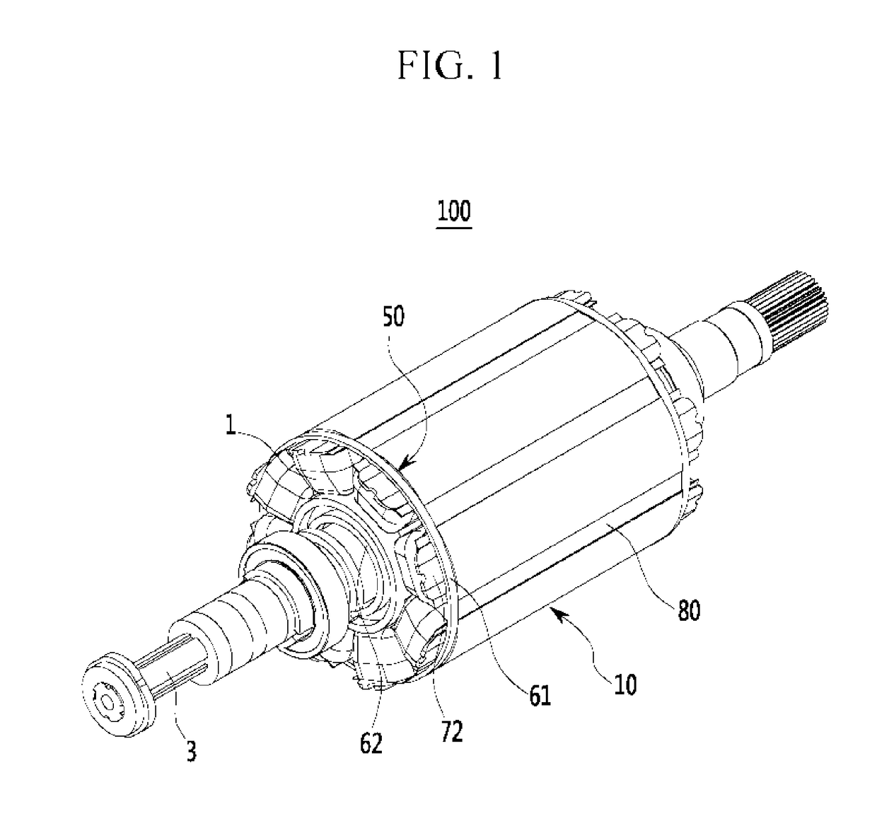
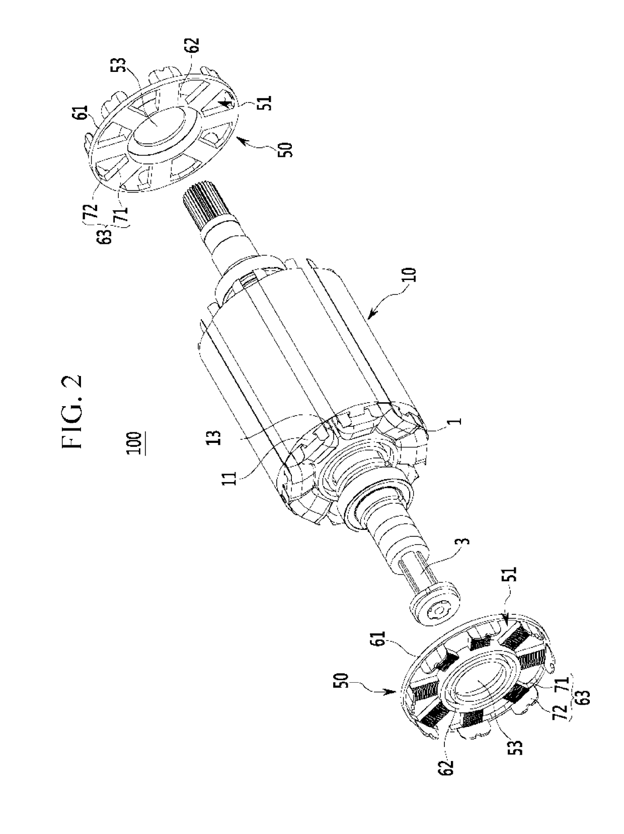
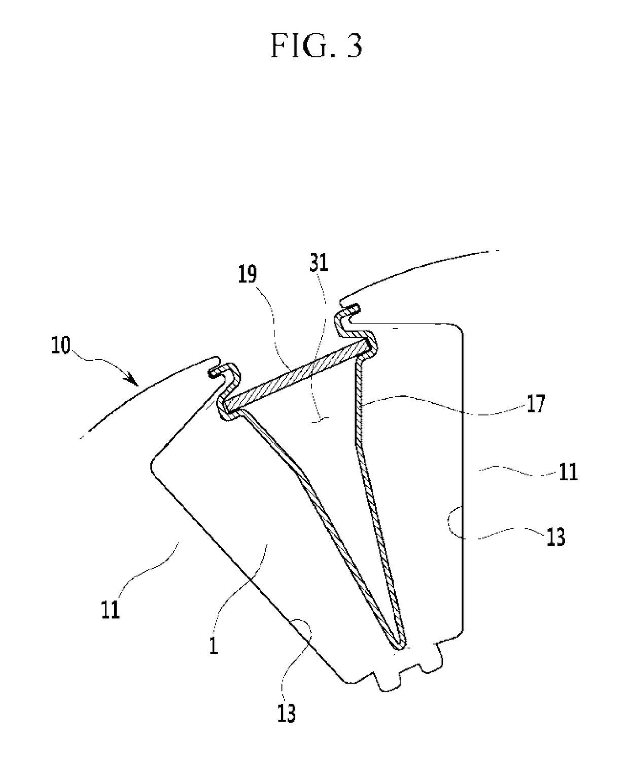
A rotor of a wound rotor driving motor is provided. The rotor includes a rotor body that is rotatably installed with a predetermined air gap within a stator and in which a rotor coil is wound in a plurality of rotor teeth. A bobbin is fixed to the rotor body by the rotor coil disposed at opposing sides of an axial direction of the rotor body and supports the rotor coil. The rotor body forms a plurality of air movement passages that are opened to the exterior in an axial direction therein, and the bobbin forms a plurality of connection passage that are coupled to the air movement passages.

Description

CROSS-REFERENCE TO RELATED APPLICATION[0001]This application claims priority to and the benefit of Korean Patent Application No. 10-2014-0172131 filed in the Korean Intellectual Property Office on Dec. 3, 2014, the entire contents of which are incorporated herein by reference.BACKGROUND[0002](a) Field of the Invention[0003]The present invention relates to a wound rotor driving motor and more particularly, to a rotor cooling structure of a wound rotor driving motor that cools a rotor coil with external air as an open structure of a non-molding method.[0004](b) Description of the Related Art[0005]In general, a hybrid electric vehicle or an electric vehicle generates driving torque using an electric motor (hereinafter referred to as a “drive motor”) that develops torque with electrical energy. For example, a hybrid electric vehicle may be driven in an electric vehicle (EV) mode, which is a pure electric vehicle mode where power of a drive motor is used, or in a hybrid electric vehicle ...

Claims


Application Information

Patent Timeline
Patent Type & Authority Patents(United States)
IPC IPC(8): H02K3/52H02K3/34H02K3/24H02K1/32H02K9/02
CPCH02K3/24H02K9/02H02K3/527H02K1/325H02K1/32
Inventor YANG, HONG SEOKPARK, SANGJINLEE, JUNGWOO
Owner HYUNDAI MOTOR CO LTD
Learn More