Mechanical link with single coil flexible member accommodating multiple-axis rotation

a flexible member and mechanical link technology, applied in the direction of wound springs, machines/engines, couplings, etc., can solve the problems of reducing design flexibility, increasing complexity, cost and weight, etc., and achieve the effect of robust and cost-effectiv

Active Publication Date: 2018-12-18
ULTRA PCS LTD
View PDF37 Cites 3 Cited by
  • Summary
  • Abstract
  • Description
  • Claims
  • Application Information

AI Technical Summary

Benefits of technology

[0007]The mechanical link of the present invention is capable of guiding and protecting a flexible member such as a conductor, hose or the like as the arms rotate about mutually orthogonal first and second axes simultaneously. Thus, the mechanical link permits complex three dimensional movement of interconnected structures, whilst protecting and guiding the flexible member. The coiled portion of the flexible member permits the flexible member to coil and uncoil in order to accommodate rotation about the first axis, and to twist in order to accommodate rotation about the second axis. Thus, the mechanical link provides a robust and cost effective solution to the problem of guiding a flexible member between structures that are required to perform complex three dimensional movements relative to each other.

Problems solved by technology

However, these solutions typically only accommodate movement about one axis at a time.
Thus, where simultaneous movement about multiple axes is required, multiple separate joints are required, which increases complexity, cost and weight, whilst also reducing design flexibility.

Method used


Image

  • Mechanical link with single coil flexible member accommodating multiple-axis rotation
  • Mechanical link with single coil flexible member accommodating multiple-axis rotation
  • Mechanical link with single coil flexible member accommodating multiple-axis rotation

Examples


Embodiment Construction

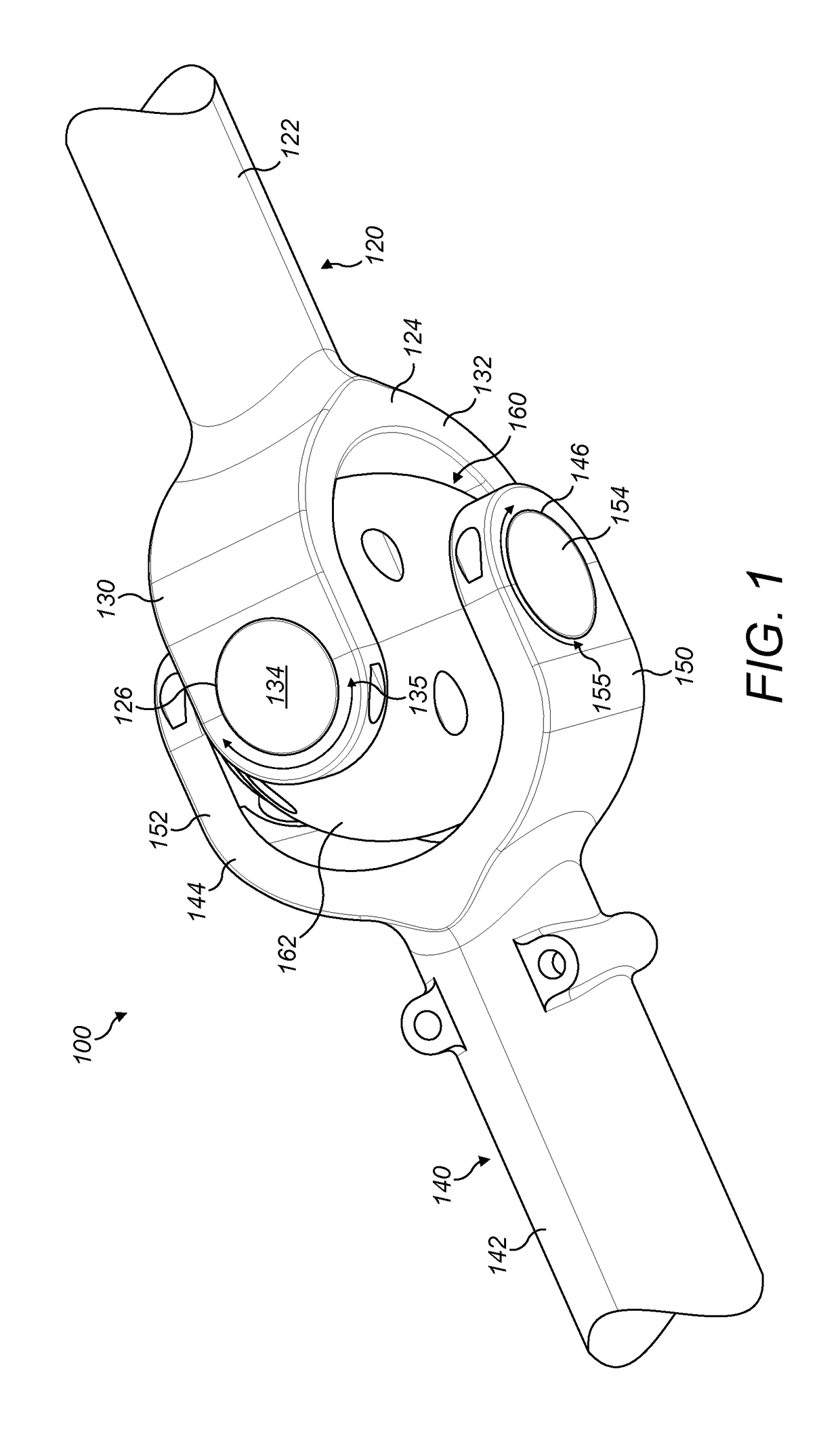
[0032]Referring first to FIG. 1, a mechanical link is shown generally at 100. In the example described below and illustrated in the accompanying Figures the mechanical link 100 guides and protects a flexible conductor, but it will be appreciated by those skilled in the art that the principles described herein can be applied to other types of

[0033]flexible members, including, for example, cables, pneumatic and hydraulic hoses, fiber optic cables and the like.

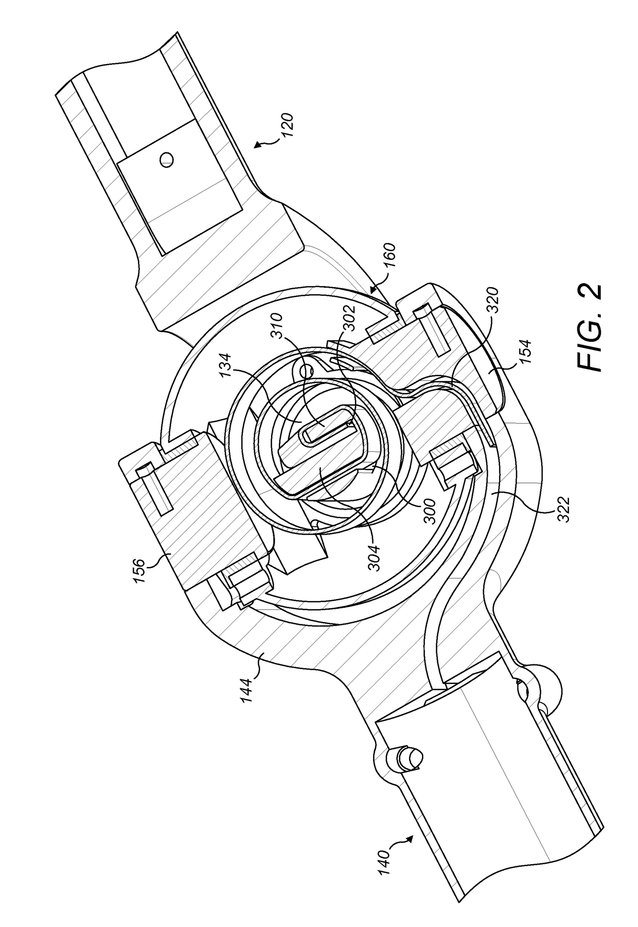
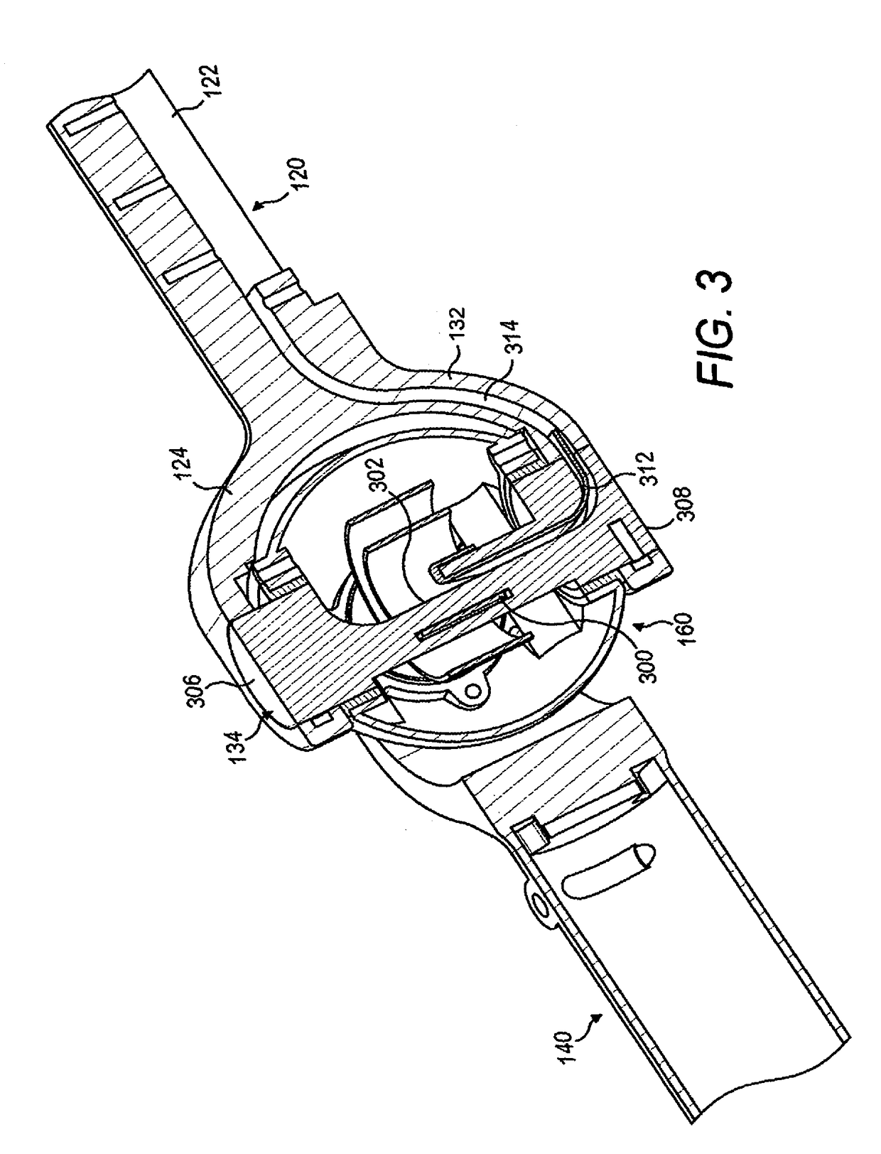
[0034]The mechanical link 100 is configured as a universal joint, and comprises a first arm 120, a second arm 140 and an interconnection member 160. The first arm 120 takes the form of a generally hollow shaft 122 which terminates in a first open yoke 124. The second arm 140 takes the form of a generally hollow shaft 142 which terminates in a second open yoke 144. The interconnection member 160 is received between the first and second yokes 124, 144 so as to link the first arm 120 to the second arm 140.

[0035]Generally circular ap...


PUM


Abstract

A mechanical link (100, FIG. 5), the mechanical link comprising a first arm (120), a second arm (140) and an interconnection member (160), wherein: the first arm is rotatable about a first axis of the interconnection member; the second arm is rotatable about a second axis of the interconnection member, the second axis being orthogonal to the first axis; and wherein: a flexible member (400) extends along the first and second arms and is adapted to accommodate rotation of the arms about the first and second axes, the flexible member having a single coiled portion (440) which is received within the interconnection member such that the coiled portion can coil and uncoil to accommodate rotation of the first arm, wherein the coiled portion is further configured to twist about an axis of the flexible member to accommodate rotation of the second arm.

Description

CROSS-REFERENCE TO RELATED APPLICATION[0001]This application claims priority pursuant to 35 U.S.C. § 119(b) to Great Britain application Serial No. GB1609381.7 filed May 27, 2016, which is hereby incorporated by reference, in its entirety.TECHNICAL FIELD[0002]The present application relates to a mechanical link for guiding and protecting a flexible member such as a conductor, cable, hose or the like.BACKGROUND TO THE INVENTION[0003]There are numerous applications in which it is necessary to guide a flexible member such as an electrical conductor or cable, hydraulic hose or the like between two structures, where one structure is moveable relative to the other. For example, in the aerospace industry it is a common requirement for an electrical cable to provide power to components on moveable control surfaces, whilst in the automotive industry electrical conductors are commonly required to provide power to components in doors, wing mirrors and the like. In all of these applications the...

Claims


Application Information

Patent Timeline
Patent Type & Authority Patents(United States)
IPC IPC(8): F16C11/12F16D3/38F16C11/06F16L3/015E05D11/00B60R16/08B60R16/03B60R16/027F16F1/04F16D3/32F16D3/28F01C1/063H01R39/64
CPCF16C11/12B60R16/027B60R16/03B60R16/08E05D11/0081F01C1/063H01R39/643F16D3/28F16D3/32F16D3/38F16D3/387F16F1/04F16L3/015F16C11/06
Inventor KEEN, PHIL
Owner ULTRA PCS LTD
Why Eureka
Try Eureka