Endoscope with lateral illumination, use and method

Inactive Publication Date: 2015-08-13
OLYMPUS WINTER & IBE
View PDF7 Cites 2 Cited by
  • Summary
  • Abstract
  • Description
  • Claims
  • Application Information

AI Technical Summary

Benefits of technology

[0014]For the arrangement of the light-emitting diode or the light-emitting diodes, it is advantageous that the light-emitting diode or the light-emitting diodes is/are embedded in the outer tube or in a housing, which is arranged distally on the endoscope shaft. In the case of an embedding in the circumference either in the outer tube or in the corresponding housing on the distal tip, the LED or the LEDs do not protrude over the circumference of the endoscope shaft and thus do not form an obstacle. They can be protected for example by a transparent coat of paint or by a transparent film or a transparent tube.
[0015]Several light-emitting diodes are advantageously arranged symmetrically around the pivot plane. The outer light diode

Problems solved by technology

However, a satisfactory solution for endoscopes with pivotable optics, which also have lateral viewing directions, up to for example 90°, has not yet been found.
Within the available res

Method used


Image

  • Endoscope with lateral illumination, use and method
  • Endoscope with lateral illumination, use and method

Examples


Example

[0026]In the drawings, the same or similar types of elements and / or parts are provided with the same reference numbers so that a re-introduction is omitted.

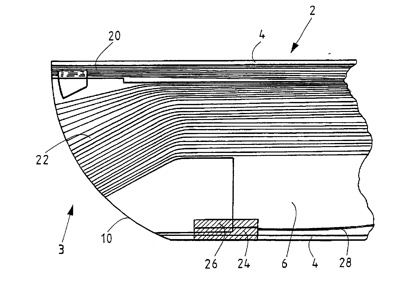
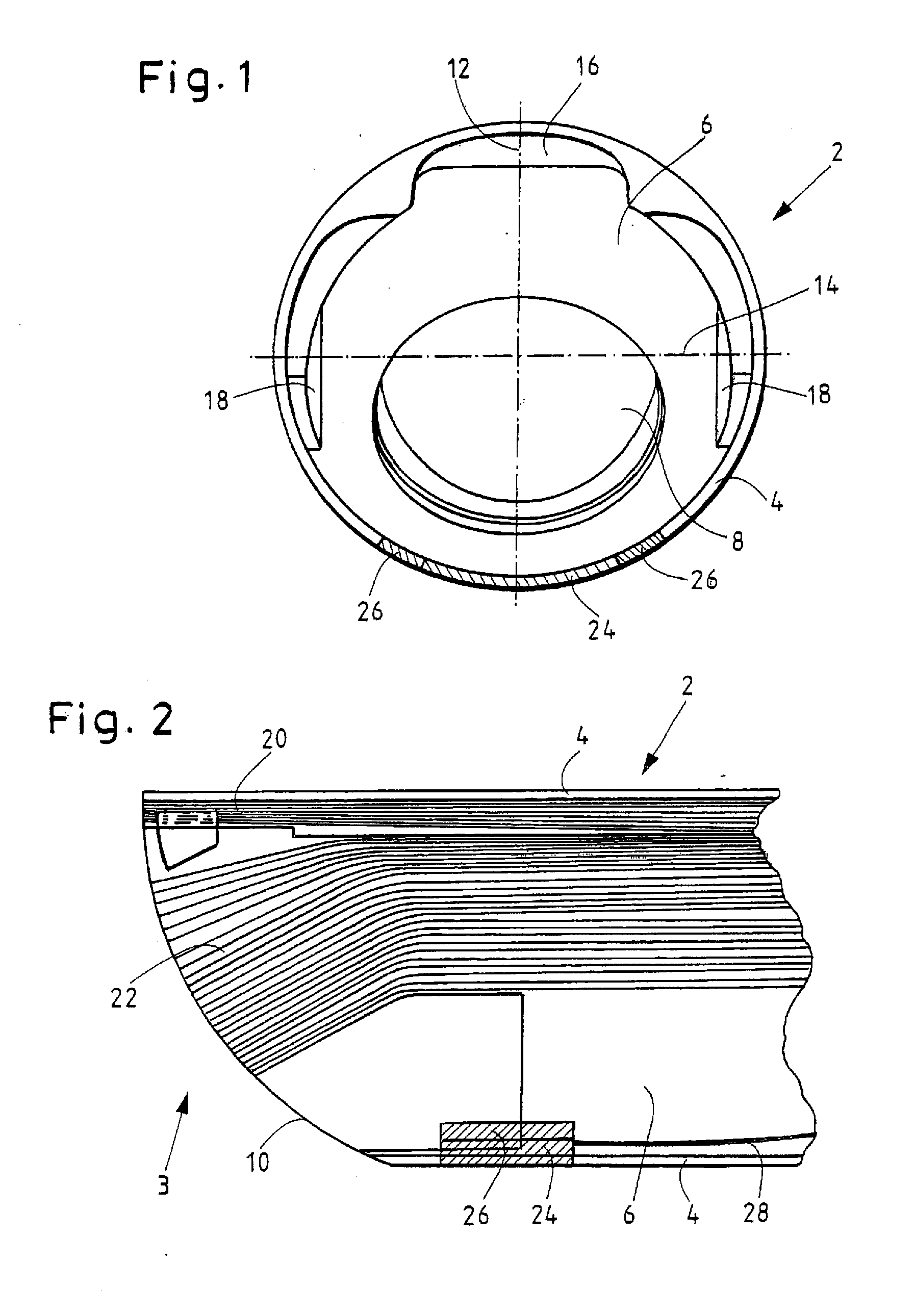
[0027]FIG. 1 shows schematically in cross-section an endoscope shaft 2 of an endoscope according to the invention in the area of the distal tip 3. A fiber tube 6, which has on one side a window opening 8 for an optical assembly and on the other side an upper outlet opening 16 and lateral outlet openings 18 for illumination optical-fiber bundles, is arranged within an outer tube 4. The diameter of the optical assembly, which is set in the window opening 8, is smaller than the diameter of the endoscope shaft 2 and is set in offset with respect to the edge so that there is space around the window opening 8 for the outlet opening 16, 18 for the illumination of an operative field in front of the distal tip of the endoscope.

[0028]The optical assembly, which is to be inserted into the window opening 8, can be a rigidly laterally looking...


PUM


Abstract

An endoscope with lateral illumination including: an endoscope shaft with an outer tube; an input lens arranged in a distal area of the outer tube, the input lens having a viewing direction pivotable in at least one pivot plane; two or more illumination optical-fiber bundles terminating at output surfaces at a distal tip, wherein a first illumination optical-fiber bundle generates an illumination, at a 0° viewing angle, and a second illumination optical-fiber bundle generates an illumination of another area with a lateral viewing angle or lateral viewing-angle range of between 0° and 90°; and one or more light-emitting diodes arranged in or on a circumference of the endoscope shaft in an area of the distal tip, wherein the light-emitting diode(s) is/are arranged in the pivot plane and/or around the pivot plane, in order to generate an illumination at a viewing angle or a viewing-angle range of about 90°.

Description

CROSS-REFERENCE TO RELATED APPLICATION[0001]The present application is a continuation of PCT / EP2013 / 003004 filed on Oct. 7, 2013, which is based upon and claims the benefit to DE 10 2012 219 434.7 filed on Oct. 24, 2012, the entire contents of each of which are incorporated herein by reference.BACKGROUND[0002]1. Field[0003]The present application relates to an endoscope with lateral illumination, having an elongated endoscope shaft with an outer tube, in the distal area of which is arranged an input lens with a viewing direction pivotable in at least one pivot plane, wherein the endoscope shaft accommodates one or more illumination optical-fiber bundles, which terminate at output surfaces at a distal tip of the endoscope shaft, wherein at least a first illumination optical-fiber bundle generates an illumination, at a 0° viewing angle, of an area lying in front of the distal tip of the endoscope shaft, and at least a second illumination optical-fiber bundle generates an illumination ...

Claims


Application Information

Patent Timeline
IPC IPC(8): A61B1/06A61B1/07
CPCA61B1/0623A61B1/0638A61B1/0684A61B1/07A61B1/0615A61B1/0676G02B23/2423G02B23/2469A61B1/00183A61B1/0605A61B1/0625A61B1/0627A61B1/0655
Inventor SCHOUWINK, PETER
Owner OLYMPUS WINTER & IBE
Why Eureka
Try Eureka