Plunger Rod Retaining Anchors

a technology of retaining anchors and plunger rods, which is applied in the field of plunger rods, can solve the problems of high molding cycle time, large amount of material required to mold, and various deficiencies of current retaining rings provided on conventional plunger rods, so as to improve the moldability of plunger rods, reduce overall material use, and reduce the geometry. complex

Inactive Publication Date: 2013-05-16
BECTON DICKINSON & CO
View PDF7 Cites 3 Cited by
  • Summary
  • Abstract
  • Description
  • Claims
  • Application Information

AI Technical Summary

Benefits of technology

[0010]An object of the present invention is to provide a plunger rod having a feature for preventing the plunger rod from being removed from the syringe barrel. More specifically, a need exists for a plunger rod that includes a plurality of retaining anchors to replace the conventional retaining ring. The use of such retaining anchors reduces overall material use by 3%-5%, thereby yielding a “greener” syringe. In addition, using these retaining anchors instead of the conventional retaining ring leads to improved plunger rod moldability due to the less complex geometry and a reduction in the number of knockout pins required to eject the plunger rod from the mold which makes the mold more cost effective and robust.

Problems solved by technology

The current retaining ring provided on conventional plunger rods suffers from various deficiencies.
For instance, a large amount of material is required to mold such plunger rods that include retaining rings.
In addition, due to the complex geometry of such plunger rods, the molding of these items requires a large number of knockout pins to eject the molded plunger rod from the mold and a high molding cycle time.

Method used


Image

  • Plunger Rod Retaining Anchors
  • Plunger Rod Retaining Anchors
  • Plunger Rod Retaining Anchors

Examples


Embodiment Construction

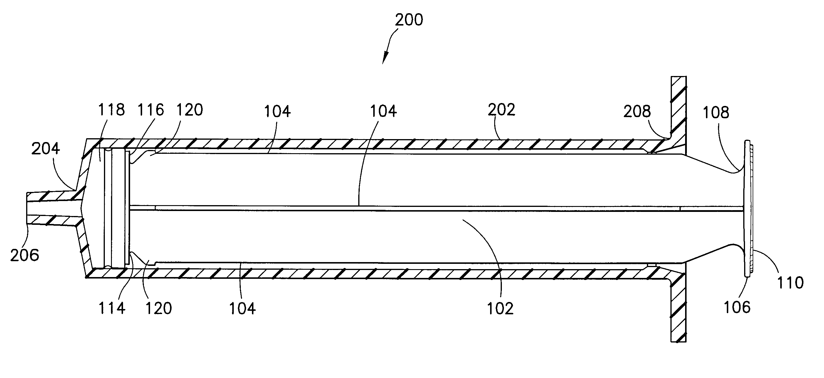
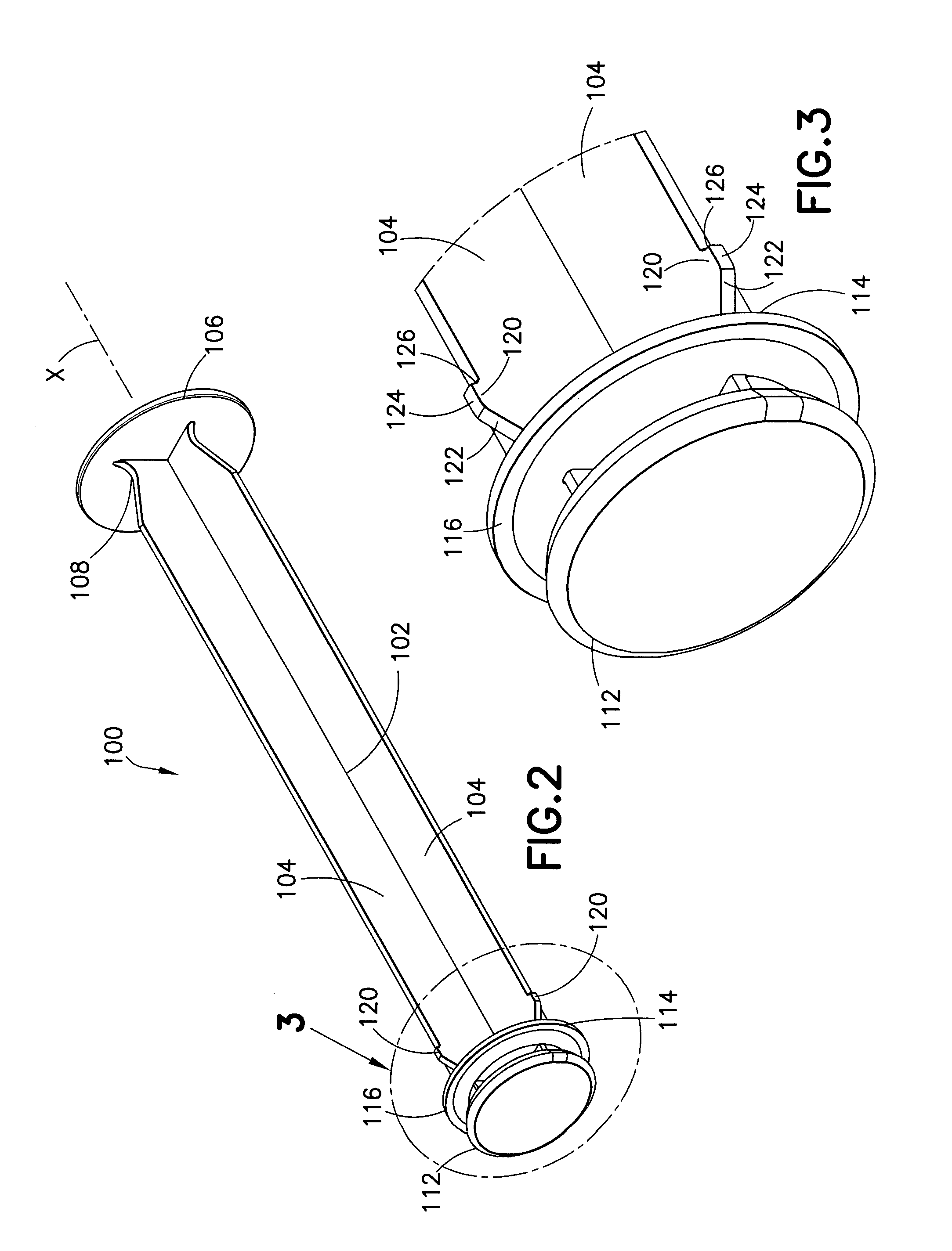
[0026]For purposes of the description hereinafter, the terms “upper”, “lower”, “right”, “left”, “vertical”, “horizontal”, “top”, “bottom”, “lateral”, “longitudinal”, and derivatives thereof, shall relate to the invention as it is oriented in the drawing figures. However, it is to be understood that the invention may assume various alternative variations, except where expressly specified to the contrary. It is also to be understood that the specific devices illustrated in the attached drawings, and described in the following specification, are simply exemplary embodiments of the invention. Hence, specific dimensions and other physical characteristics related to the embodiments disclosed herein are not to be considered as limiting.

[0027]With reference to FIGS. 2-4, a plunger rod, generally denoted as reference numeral 100, includes an elongated body 102 formed by orthogonally spaced elongated ribs 104 extending along a longitudinal axis X. A first ledge 106 is provided at a first end ...


PUM


Abstract

A plunger rod includes: an elongated body formed by a plurality of orthogonally spaced elongated ribs extending along a longitudinal axis; a first ledge adjacent a first end of the elongated body; a second ledge adjacent a second end of the elongated body; and an attachment portion extending from the second ledge. The second end of the elongated body opposes the first end of the elongated body. At least one elongated rib includes a retaining anchor positioned adjacent the second end adjacent the second ledge.

Description

BACKGROUND OF THE INVENTION[0001]1. Field of the Invention[0002]The invention relates, in general, to a plunger rod for use with a syringe and, more particularly, to a plunger rod that includes a plurality of anchors around the circumference thereof to prevent the plunger rod from being pulled out of the syringe barrel during aspiration of the syringe.[0003]2. Description of Related Art[0004]Current syringe designs can typically be categorized as two-piece syringes or three-piece syringes. A typical three-piece syringe includes a tubular barrel having an access opening formed at one end, and a smaller discharge opening formed at the opposing end. The lead end of an elongated plunger rod is received within the access opening of the barrel so as to be slidable within the barrel. Attached to the lead end of the plunger rod is a flexible sealing member or stopper that snugly seals against the interior surface of the barrel. A needle, a threaded member, or a non-threaded member is usuall...

Claims


Application Information

Patent Timeline
Patent Type & Authority Applications(United States)
IPC IPC(8): A61M5/315
CPCA61M5/31511A61M5/31501A61M2005/31508A61M2005/31506
Inventor IVOSEVIC, MILAN
Owner BECTON DICKINSON & CO
Why Eureka
Try Eureka