Tank circuit and frequency hopping for isolators

Active Publication Date: 2018-12-25
ANALOG DEVICES INT UNLTD
View PDF29 Cites 2 Cited by
  • Summary
  • Abstract
  • Description
  • Claims
  • Application Information

AI Technical Summary

Problems solved by technology

Existing circuits to transmit power from one domain to another, while maintaining galvanic isolation, suffer from a variety of drawbacks.
For example, some convention

Method used


Image

  • Tank circuit and frequency hopping for isolators
  • Tank circuit and frequency hopping for isolators
  • Tank circuit and frequency hopping for isolators

Examples


Example

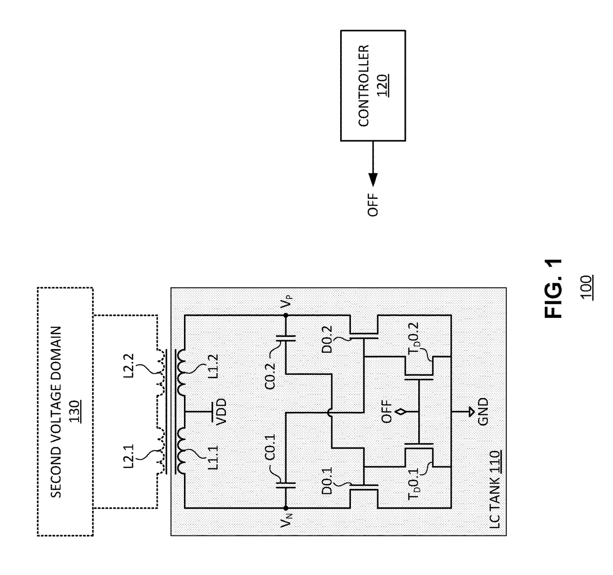
[0009]Embodiments of the present disclosure may provide a circuit comprising a tank circuit. The tank circuit may include an inductor having a pair of terminals, a first pair of transistors, and a first pair of capacitors. Each transistor may be coupled between a respective terminal of the inductor and a reference voltage along a source-to-drain path of the transistor. Each capacitor may be provided in a signal path between an inductor terminal coupled to a respective first transistor in the first pair and a gate of a second transistor in the first pair.

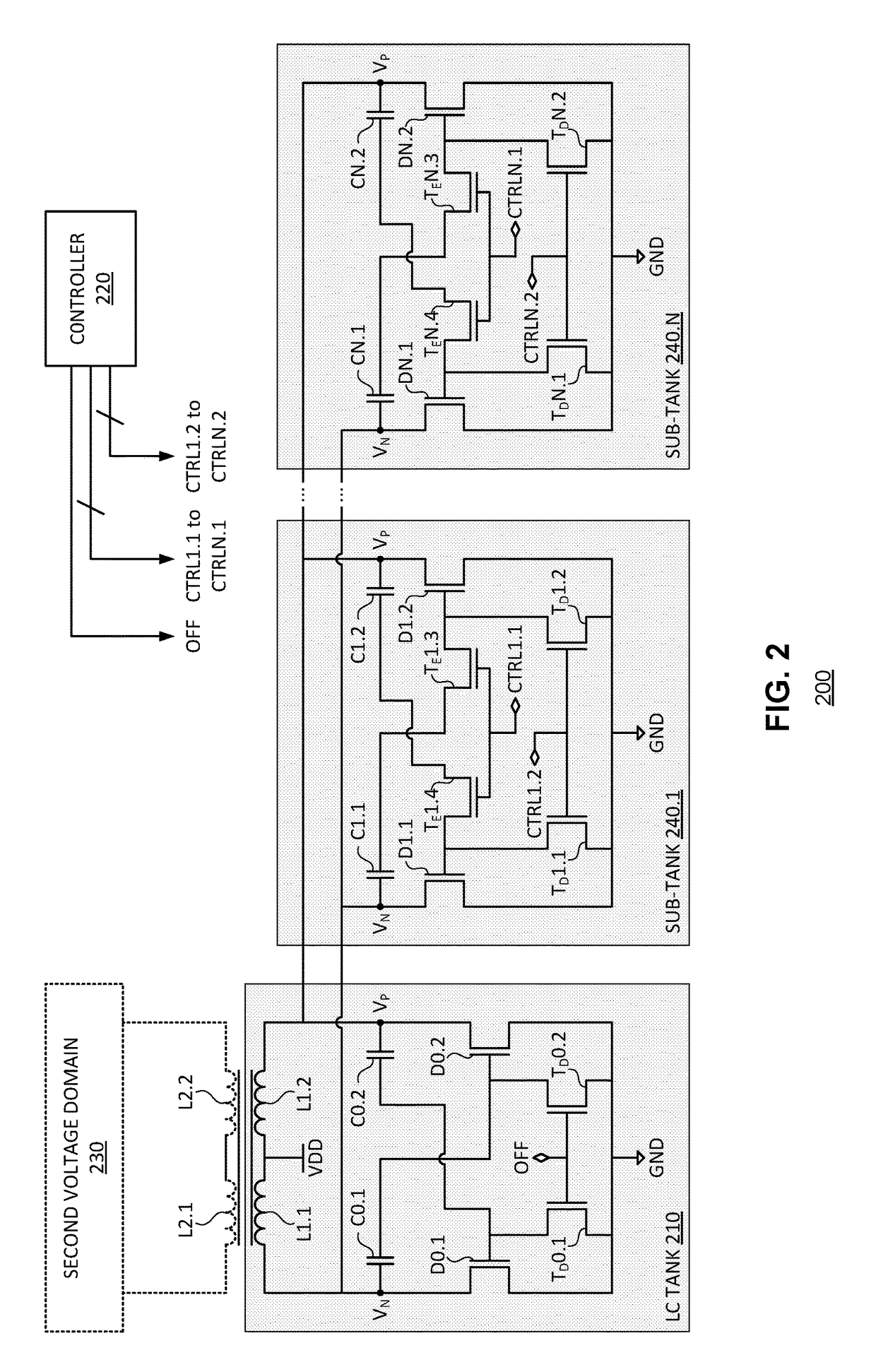
[0010]Embodiments of the present disclosure may provide controller method for generating an oscillation frequency. The method may include at a first time instance: activating a first pair of transistors of the tank circuit, each coupled between a respective terminal of an inductor having a pair of terminals and a reference voltage along a source-to-drain path of the transistor; coupling, as a result of the activating, a first of a pa...


PUM


Abstract

Embodiments of the present disclosure may provide a circuit comprising a tank circuit. The tank circuit may include an inductor having a pair of terminals, a first pair of transistors, and a first pair of capacitors. Each transistor may be coupled between a respective terminal of the inductor and a reference voltage along a source-to-drain path of the transistor. Each capacitor may be provided in a signal path between an inductor terminal coupled to a respective first transistor in the first pair and a gate of a second transistor in the first pair.

Description

BACKGROUND[0001]The present disclosure generally relates to circuits for transmitting power across an isolation barrier and applying frequency hopping for power transmission.[0002]Some integrated circuits include two or more voltage domains that are galvanically isolated from one another. In such integrated circuits, it may be desirable to transmit power from one domain to another. Existing circuits to transmit power from one domain to another, while maintaining galvanic isolation, suffer from a variety of drawbacks. For example, some conventional tank circuits use cross-coupled metal oxide semiconductor (MOS) transistors, which lead to poor efficiency and poor electromagnetic interference (EMI) performance.[0003]Therefore, the inventors recognized a need in the art for circuits and methods to efficiently transmit power between galvanically-isolated domains and improve EMI performance.BRIEF DESCRIPTION OF THE DRAWINGS[0004]FIG. 1 illustrates an oscillator circuit according to an emb...

Claims


Application Information

Patent Timeline
IPC IPC(8): H03B5/12H03K3/013H03B5/08
CPCH03K3/013H03B5/08H03B5/12H03B5/1296H03B5/1231H03B5/1253H03B5/1265H03B5/1228H03B5/04H03B2200/0072H03B2201/0266H01L2224/48137
Inventor YANG, XINZHAO, TIANTINGCHEN, BAOXING
Owner ANALOG DEVICES INT UNLTD
Why Eureka
Try Eureka