
Irrigation monitoring system and method for monitoring flow rate into irrigation system to determine the existence or absence of an irrigation fault

a technology of irrigation system and flow rate, applied in the field of irrigation system, to achieve the effect of improving irrigation performan

Active Publication Date: 2019-01-01
LEMKIN MARK ALAN
View PDF10 Cites 8 Cited by
  • Summary
  • Abstract
  • Description
  • Claims
  • Application Information

AI Technical Summary

Benefits of technology

The patent text describes an irrigation system monitor that helps users save water by detecting leaks and providing real-time information about the system performance. Users can then adjust their irrigation scheduling based on the monitor's feedback, reducing the amount of water wasted. The monitor can also alert users about potential leaks and perform necessary repairs or adjustments. Overall, the system monitor improves the user's understanding of the irrigation system and allows them to manage it more efficiently.

Problems solved by technology

Open-loop irrigation is disadvantageous due to the lack of insight into the actual flow and total water delivered.
Irrigation systems are typically subject to a large number of failure modes that may occur without notice until large expenses have already been incurred (e.g. death or injury of plants due to insufficient or excess water delivery; a large water bill due to excess irrigation.)
TABLE 1Common Irrigation Failure ModesPipe breakMalfunctioning valveDrip line damage caused by line trimmers.Sprinkler head cloggedSprinkler head damaged by lawnmowerEmitters or line disconnection due to tripping or diggingfrom people or animalsChewing animals resulting in leaks, excess watering, ordamaged emittersClogged emitters resulting in a reduced flow of waterValves don't turn off due to a flow rate that is too lowValves don't turn on due to a poor electrical connection(shorts / opens due to grease caps)Tampering with irrigation settingsDamage due to freezing or improper weatherizationStuck solenoid
A user generally doesn't know about an irrigation system failure to water until plants have died and / or shown signs of water stress, which can be too late since water stress can damage or weaken plants.
Many irrigation leaks are only discovered when the next water bill arrives, at which point much water has been wasted and charges already accrued.
In many localities invoices for water service are processed only every 3 months—thus wasted water may continue for three months before even being noticed at which point a repair needs to be scheduled and performed.
Irrigation systems that operate without close attention to irrigation performance and / or frequent inspections (e.g. parks, city developments, schools, buildings etc.) are particularly susceptible to operation under a failure condition since the system owner or user may not be aware of irrigation failures unless they are there when the zone is actively being watered.
In the open-loop irrigation case it is difficult to know where a leak is in the system even once a leak is inferred from a large water bill.
In residential installations, given solely the information that excess water was used during a billing period, it isn't clear if an irrigation leak was intermittent (intermittently-sticky valve stuck open—could spend hours trying to isolate to no avail), permanent, or even what zone the leak is in; it can be very cumbersome to determine root-cause after the fact when presented with a large water bill.
Thus, investigation of excess water consumption is only initiated when a large water bill is received, and can be very time consuming.
Poor intuition of delivered water volume often leads to the controller being programmed longer than is necessary by the user, “just to be safe”.

Method used


Image

  • Irrigation monitoring system and method for monitoring flow rate into irrigation system to determine the existence or absence of an irrigation fault
  • Irrigation monitoring system and method for monitoring flow rate into irrigation system to determine the existence or absence of an irrigation fault
  • Irrigation monitoring system and method for monitoring flow rate into irrigation system to determine the existence or absence of an irrigation fault

Examples


Embodiment Construction

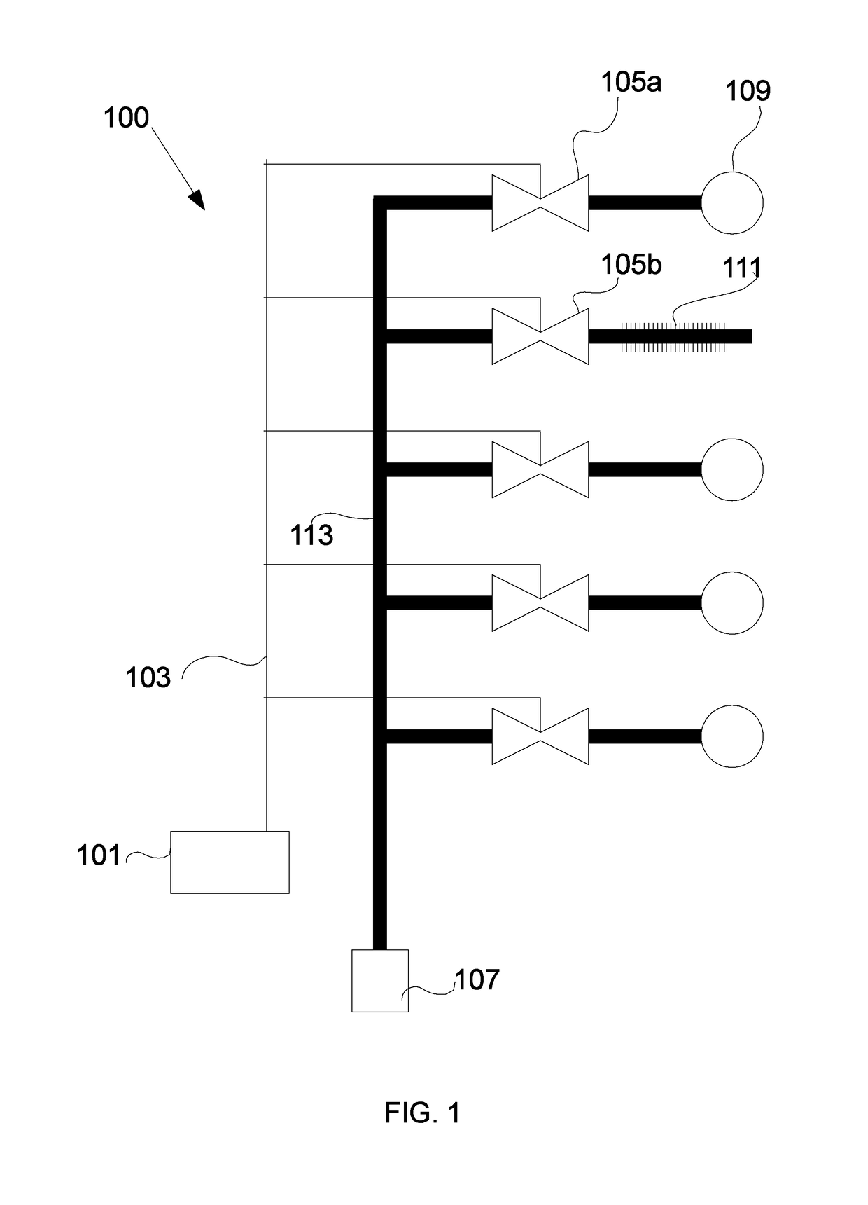
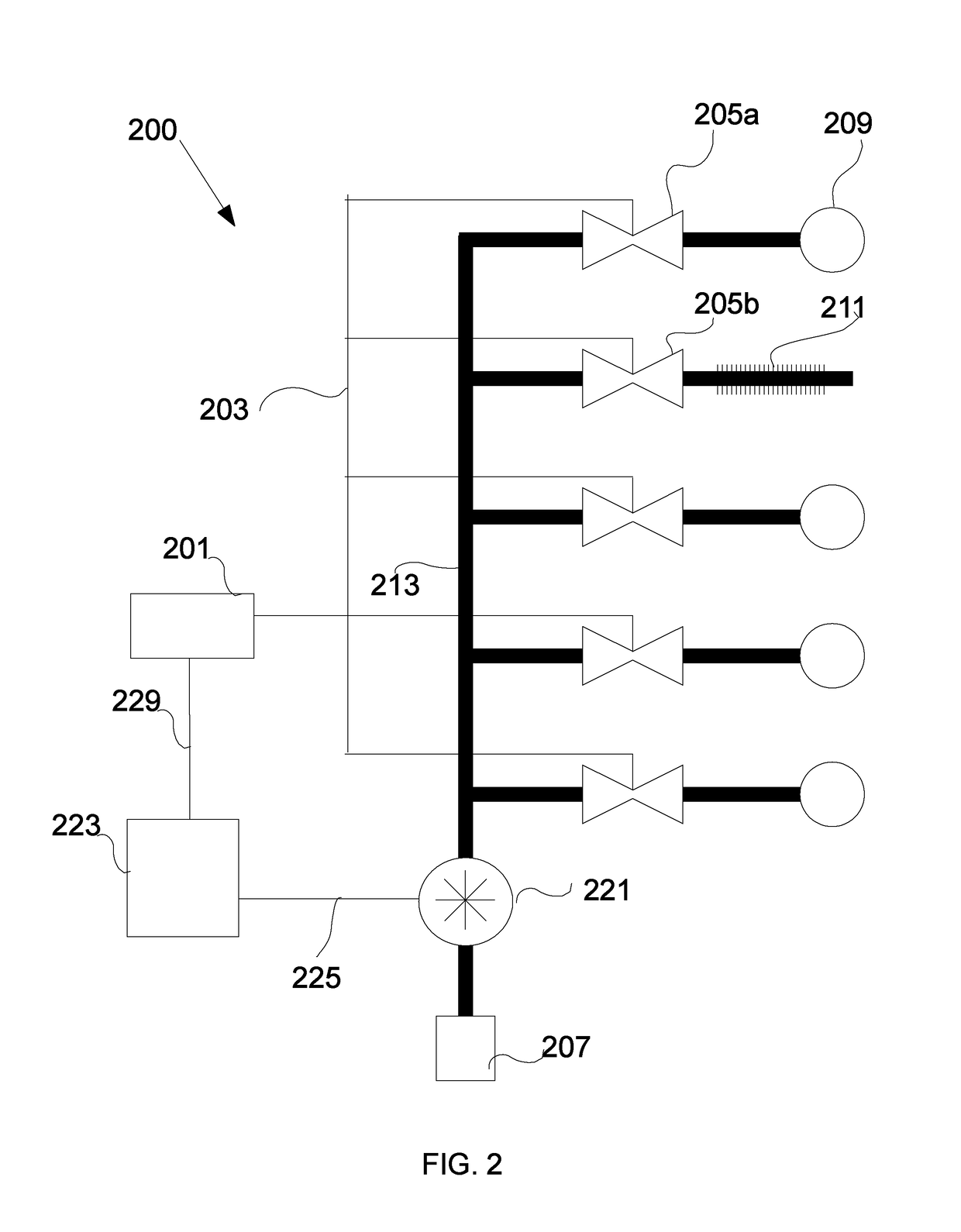
[0031]Irrigation systems are commonly partitioned into a plurality of zones for various reasons including differences in vegetation, soil, micro-climate, or to provide a lower peak water flow for satisfying restrictions on water delivery (e.g. so as not to exceed a water pumping capacity supplied by a well or a maximum flow-rate of a service line). With reference to FIG. 1, in some embodiments irrigation system 100 has an irrigation controller 101 which connects via wires 103 to remotely located valves 105a and 105b; in some embodiments the valves are located proximate the irrigation controller and water distribution occurs via piping from the valves. The irrigation valves 105a,b are solenoid-actuated and, in some embodiments, control flow using a diaphragm to initiate and terminate watering as determined by the controller. Energy is provided to each valve's solenoid via two conductors: one conductor is commonly shared among multiple valves as a common terminal; the other conductor ...


PUM


Abstract

A method and device for monitoring an irrigation system is provided. The device includes a flow sensor and an irrigation controller comprising at least two outputs. The irrigation monitor is coupled to the irrigation controller and the flow sensor and performs an action in response to detecting a fault condition. The method includes steps of measuring flow through an irrigation feed, determining an intended state of an irrigation valve, associating the measured flow with the intended valve state, and detecting a fault condition. In some examples the irrigation monitor and irrigation controller use a single processor.

Description

TECHNICAL FIELD[0001]This disclosure generally relates to the electrical and mechanical arts, and more particularly to irrigation systems.DESCRIPTION OF RELATED ART[0002]Conventional irrigation systems operate based on a schedule, opening and closing irrigation valves controlling multiple irrigation zones according to this schedule. Some conventional irrigation systems modify the schedule based upon weather or precipitation to provide an amount of water more closely in tune with the needs of the irrigated zone. For various reasons, many irrigation systems are broken into multiple zones where a single irrigation controller is responsible for opening and closing multiple valves electrically. The valves are usually solenoid-actuated and control the flow from a water main that supplies water for the irrigation system (e.g. irrigation feed), with the individual valves controlling flow from the irrigation feed to individual zones as controlled by the irrigation controller.SUMMARY[0003]The...

Claims


Application Information

Patent Timeline
Patent Type & Authority Patents(United States)
IPC IPC(8): G05D11/00G05D9/00A01G25/16G05D7/06G05D7/00B05B12/00B05B12/08
CPCB05B12/085G05D7/0676B05B12/006A01G25/167
Inventor LEMKIN, MARK ALAN
Owner LEMKIN MARK ALAN
Learn More