Switch system and operation method thereof

a technology of switch system and operation method, which is applied in the direction of electric digital data processing, instruments, and single-core architectures, etc. it can solve the problems of reducing the time for performing the rebooting procedure, and optimizing the transmission method for transmitting signals

Active Publication Date: 2019-01-01
INVENTEC PUDONG TECH CORPOARTION +1
View PDF7 Cites 0 Cited by
  • Summary
  • Abstract
  • Description
  • Claims
  • Application Information

AI Technical Summary

Benefits of technology

[0009]As mentioned above, through the switch system and the operation method thereof apply the characteristic that the baseboard management controller gets ready very rapidly while the switch system is turned on, the baseboard management controller can write the system parameter to the corresponded switch through the transmission path provided by multiplexer, even the switch is not completely turned on. Therefore, the switch system can finish setting the related configurations of each switch before finishing the booting procedure. The invention no longer needs to load the operation system by multiple times to finish the configurations. As such, the invention achieves the effect of reducing the time of booting procedure. Besides, the baseboard management controller can adjust the signal strength for transmitting data or the adopted bandwidth interface for different demand of the transmission path. Thus, the invention provides the optimized transmission method for transmitting signal.

Problems solved by technology

However, the traditional switch system needs to write information to the electrically-erasable programmable read-only memory (EEPROM) through the PCIe bus and spend waiting time for finishing the rebooting procedure.
Besides, it will cause the PCIe bus to have the lower communication ability when the signal transmitted by PCIe bus gets weaker.
Therefore, the complete information may not be fully written to the electrically-erasable programmable read-only memory.
Therefore, how to provide an effective switch system for finishing setting all the configurations before finishing the booting procedure and reducing time for performing the rebooting procedure becomes a problem to be solved.

Method used


Image

  • Switch system and operation method thereof
  • Switch system and operation method thereof
  • Switch system and operation method thereof

Examples


Embodiment Construction

[0015]Reference will now be made in detail to the present embodiments of the invention, examples of which are illustrated in the accompanying drawings. Wherever possible, the same reference numbers are used in the drawings and the description to refer to the same or like parts.

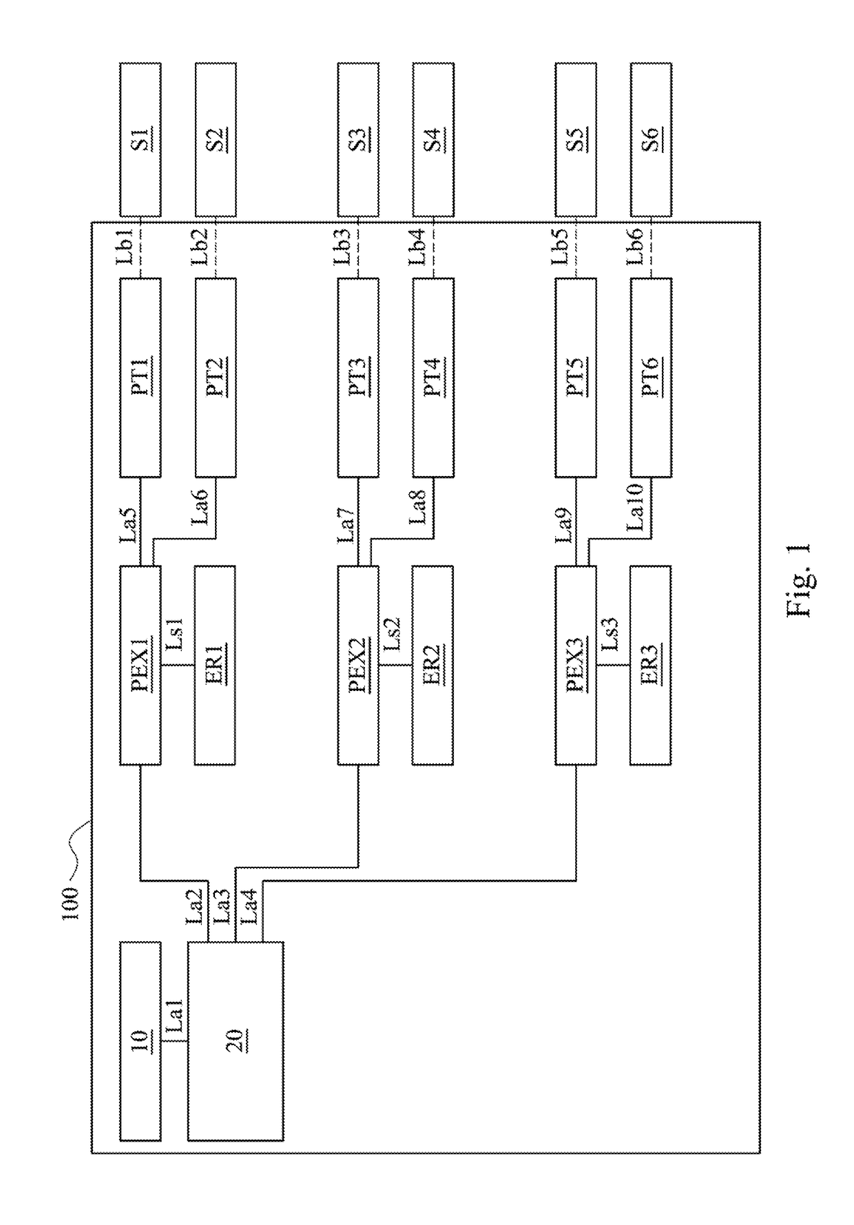
[0016]It will be understood that, although the terms “first,”“second,” etc. may be used herein to describe various elements, these elements should not be limited by these terms. These terms are only used to distinguish one element from another. For example, a first element could be termed a second element, and, similarly, a second element could be termed a first element, without departing from the scope of the embodiments. Reference is made to FIG. 1. FIG. 1 illustrates a block diagram of a switch system 100 according to an embodiment of the present invention.

[0017]In one embodiment, the switch system 100 includes a processing unit 10, a peripheral component interconnect express switch (PCIe switch) 20, multip...


PUM


Abstract

A switch system is provided. The switch system comprises a first multiplexer and a baseboard management controller (BMC). The first multiplexer is coupled to a first electrically-erasable programmable read-only memory (EEPORM). The baseboard management controller transmits a first control signal to the first multiplexer by a first multiplexer control channel. Wherein, the first control signal controls the first multiplexer coupling to a first serial peripheral interface (SPI) bus. The baseboard management controller transmits a first system parameter to the first multiplexer by the fist SPI bus. The first multiplexer writes the first system parameter by a second serial peripheral interface bus to the first electrically-erasable programmable read-only memory.

Description

CROSS-REFERENCE TO RELATED APPLICATION[0001]This application claims priority to Chinese Application Serial Number 201611050240.8, filed Nov. 24, 2016, which is herein incorporated by reference.BACKGROUND[0002]Field of Invention[0003]The present invention relates to a switch system and an operation method thereof. More particularly, the present invention relates to a switch system and an operation method thereof applying a multiplexer.[0004]Description of Related Art[0005]In general, the traditional switch system needs to wait until entering the operation system during the booting procedure for obtaining the related information from the interface of the operation system and transmitting the related information to the corresponded switch through the peripheral component interconnect express (PCIe) bus. Finally, the traditional switch system needs to be rebooted for applying all the related configurations.[0006]However, the traditional switch system needs to write information to the el...

Claims


Application Information

Patent Timeline
Patent Type & Authority Patents(United States)
IPC IPC(8): G06F15/78G06F13/42G06F13/40G06F9/4401
CPCG06F13/4022G06F13/4282G06F9/4406G06F2213/0026G06F13/126
Inventor HU, HSIANG-CHUNCHIU, CHUANG-CHUN
Owner INVENTEC PUDONG TECH CORPOARTION
Why Eureka
Try Eureka