Shielded electric connector

a shielded, electric connector technology, applied in the direction of electrical equipment, connection, coupling device connection, etc., can solve the problems of exposing users to electric shock, affecting computer and monitoring equipment, and conventionally constructed cables are not well shielded, so as to improve shielding, enhance safety and ease of use, and prevent the propagation of noise

Inactive Publication Date: 2019-01-01
SIMMONDS SIMON
View PDF8 Cites 0 Cited by
  • Summary
  • Abstract
  • Description
  • Claims
  • Application Information

AI Technical Summary

Benefits of technology

[0019]The device herein disclosed and described provides a solution to the shortcomings in prior art in high power cable connectors and achieves the above noted goals through the provision of a connector system providing rubber molded single pin high power connectors, for both the male and female connectors positioned on the ends of high power connection cables. Through a novel configuration, the disclosed system and method yields both the male and female connectors which provide significantly improved shielding at the connection point of the distal ends of cables to mating connectors, to prevent the propagation of noise from RF or EMF to equipment proximate to any such connection. At the same time, the connectors provide enhanced safety and ease of use by having a circumferential surface formed of rubber or a similar sturdy, but flexible, dielectric material. Thereby separating the metallic shielding component of the connectors from any possible contact with the hands or bodies of users handling them.
[0020]The connector system herein disclosed incorporates a copper or other conductive material to form a shield engaged with an epoxy insulated core into both the male and female cable connector bodies and with fixed female receptacle housings. An over molding process integrally bonds the copper or other conductive grounding ring providing the shielding, into the epoxy core and the surrounding rubber or similar dielectric material forming the exterior of the connector. This positively seals the conductive grounding ring into the dielectric material forming the connector assembly and prevents any risk of contact by a user. The over molding of the copper ring, within the epoxy positioned within the interior of the connector also seals against the ingress of moisture and other contaminants which might corrode the copper ring. Concurrently, this over molding construction provides mechanical rigidity and protection of the components of the connector.
[0021]The body forming the exterior of the male or female connector is formed of a sturdy dialectic material such as Hypalon rubber. This surrounding rubber exterior forms a secondary insulating layer over the primary insulator of the epoxy or other insulating ring surrounding the copper ring. The surrounding rubber or similar dielectric also provides mechanical and environmental protection.
[0023]The resulting formed male or female connector is configured for connection with all conventional electrical connectors currently used for high electric power communication using a plug engageable with a receptacle or complimentary female connector and can, thus, be easily employed without modification to the installed base of such cables and receptacles which are typically mounted on or engaged with an end of a length of cable.

Problems solved by technology

However, the introduction of such VFD AC motors has introduced a number of issues with regard to electrical power delivery.
This type of switching produces EMF fields which constantly collapse and reverse which can easily communicate noise in the system which can easily be transmitted to the cables running between the power supply and motor, and to areas proximate to the motor and supply cables.
As noted above, modernly, sensors positioned on or proximate to both the drilling component and the rig are extremely sensitive and constantly being employed to communicate real time data of the operators and engineers on the drilling rig.
The electrical noise entering the system can cause significant problems with the sensors and the communication of data therefrom over transmission lines running through or adjacent the power cables.
Such can also cause havoc with computer and monitoring equipment proximate to the rig.
However, these conventionally constructed cables are not well shielded at their respective male and female connectors, and thus can allow leakage of the noise from EMF or RF to escape to areas proximate to each connection therebetween whether employed with DC or AC power communication.
Thus, the metal casing is also a conductor and can expose the users to electric shock in some instances, such as when the surrounding conductor of the center conductor in a cable holds a charge much like a capacitor due to the long lengths such cables can reach.
Such coatings may be easily scratched and thereby expose the user to contact with the electric conductor to which the metallic casing is connected.
Such is a recipe for disaster in many instances where personnel are not familiar with electrical power issues and the proximity of sensors or delicate electronic equipment.
Various limitations of the related art will become apparent to those skilled in the art upon a reading and understanding of the specification below and the accompanying drawings.

Method used


Image

  • Shielded electric connector
  • Shielded electric connector
  • Shielded electric connector

Examples


Embodiment Construction

[0038]In this description, the directional prepositions of up, upwardly, down, downwardly, front, back, top, upper, bottom, lower, left, right and other such terms refer to the device as it is oriented and appears in the drawings and are used for convenience only; they are not intended to be limiting or to imply that the device has to be used or positioned in any particular orientation.

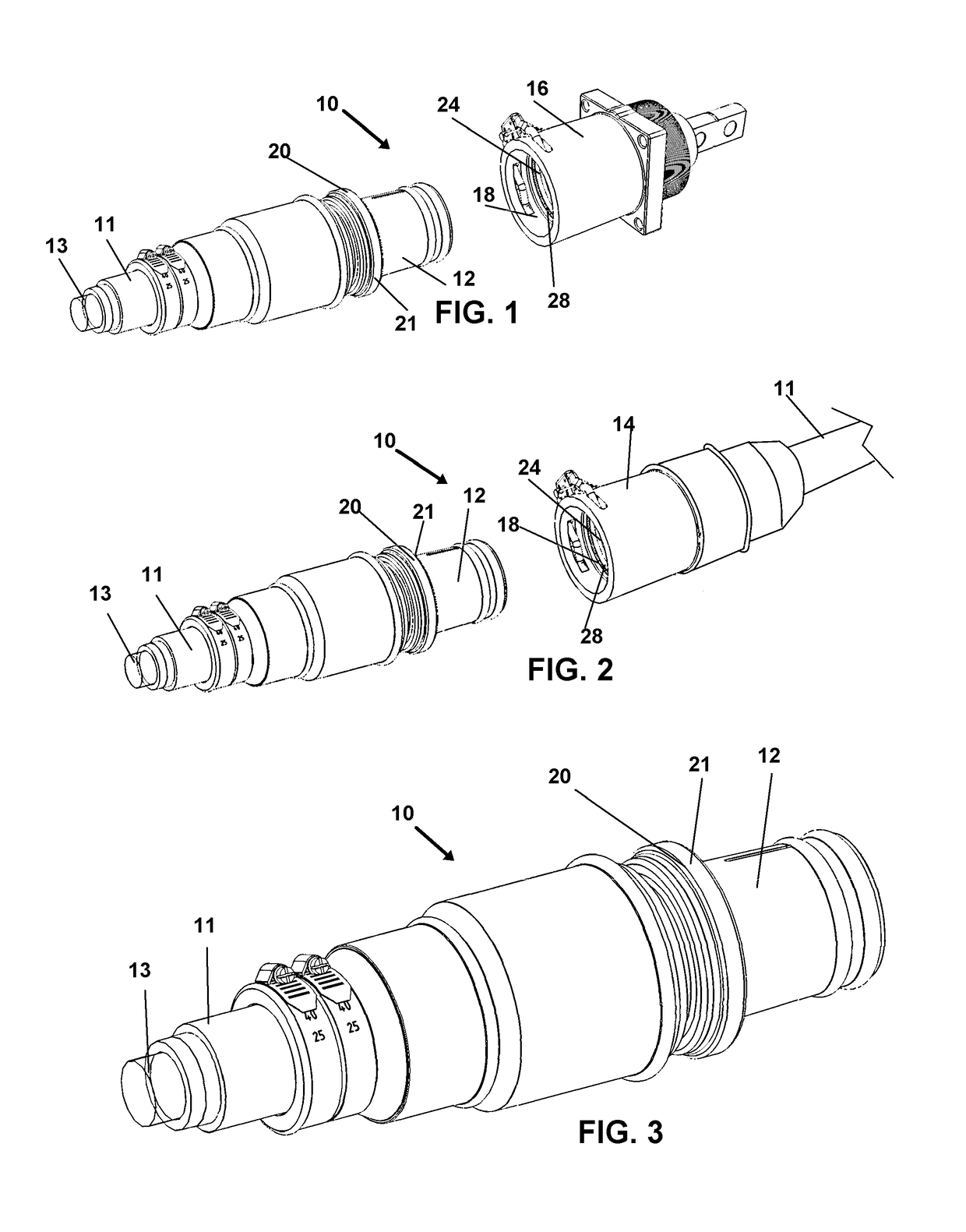
[0039]Now referring to drawings in FIGS. 1-8, wherein similar components are identified by like reference numerals, there is seen in FIG. 1 an isometric view of the connector system 10 herein, showing a first or male connector 12 positioned for operative engagement with a second or female connector 14 or female receptacle 16 of the system 10 herein disclosed. As can be seen, the first or male connector 12 is sized for operable removable engagement within an axial cavity 18 formed into the female connector 14 of FIG. 2, or the female receptacle 16 mode shown in FIG. 1, in a frictional engagement.

[0040]...


PUM


Abstract

An electrical connector system having rubber molded single pin high power conductors, for both the male and female electrical connectors positioned on the ends of high power electric connection cables. Configuration of both the male and female connectors enhances shielding at the connection point of conductors at distal ends of the electric when mating in an electric connection. The shielded connections limit electronic noise from RF or EMF which may be transmitted to equipment proximate to a shielded connection.

Description

[0001]This application claims the benefit of Provisional Application No. 62 / 333,582 filed on May 9, 2016.BACKGROUND OF THE INVENTION1. Field of the Invention[0002]The present invention relates generally to connectors for employment in the communication of power in electrical systems. More particularly, the invention relates to tri-functional shielded connectors employable for use with either a single conductor cable or multiconductor cable, such high power cables employed in oil drilling which are grounded. The system herein can also be configured in a relay-compatible mode for an additional level of safety.2. Prior Art[0003]Single-pole connectors positioned at the ends of electric cables used to communicate high power requirements are used in a variety of industrial settings such as oil and other drilling platforms, stage power requirements at concerts, and equipment requiring high power, such as carnival rides and the like. Because of the requirements of the electric motors and ot...

Claims


Application Information

Patent Timeline
Patent Type & Authority Patents(United States)
IPC IPC(8): H01R9/03H01R9/05H01R13/6593H01R13/6582H01R13/703H01R13/74H01R103/00
CPCH01R13/6582H01R9/032H01R9/0521H01R9/0524H01R13/6593H01R13/703H01R9/0527H01R2103/00H01R13/74H01R13/65912
Inventor SIMMONDS, SIMON
Owner SIMMONDS SIMON
Why Eureka
Try Eureka