Vibration wave motor and driving apparatus using the vibration wave motor

a technology of vibration wave motor and driving apparatus, which is applied in the direction of generator/motor, electrical apparatus, electric/electrostriction/magnetostriction machines, etc., can solve the problems of insufficient perpendicular direction amplitude (i) and the inability to obtain thrust force, so as to reduce the size of the vibration wave motor and the effect of downsizing the driving apparatus

Inactive Publication Date: 2019-01-01
CANON KK
View PDF20 Cites 37 Cited by
  • Summary
  • Abstract
  • Description
  • Claims
  • Application Information

AI Technical Summary

Benefits of technology

[0020]Thus, an object of the present invention is to reduce a size of a vibration wave motor in a movement direction without losing a thrust force so as to achieve downsizing of a driving apparatus by using the vibration wave motor.
[0023]With the above-mentioned measures, the size of the vibration wave motor in the movement direction may be reduced without losing a thrust force so as to achieve downsizing of the driving apparatus by using the vibration wave motor.

Problems solved by technology

As described below, however, the related-art vibration wave motor has a limitation to downsize the apparatus.
Further, as a result of reduction of the amplitude in a perpendicular direction indicated by (i) in FIG. 21A to FIG. 21D, the amplitude in the perpendicular direction (i) is insufficient for a surface roughness of a slider.
Thus, it is also predicted that there arises a problem in that the thrust force cannot be obtained.
With the configuration of the related-art vibration wave motor, however, it is difficult to reduce the size of the vibration wave motor in the movement direction without losing the thrust force.

Method used


Image

  • Vibration wave motor and driving apparatus using the vibration wave motor
  • Vibration wave motor and driving apparatus using the vibration wave motor
  • Vibration wave motor and driving apparatus using the vibration wave motor

Examples


first embodiment

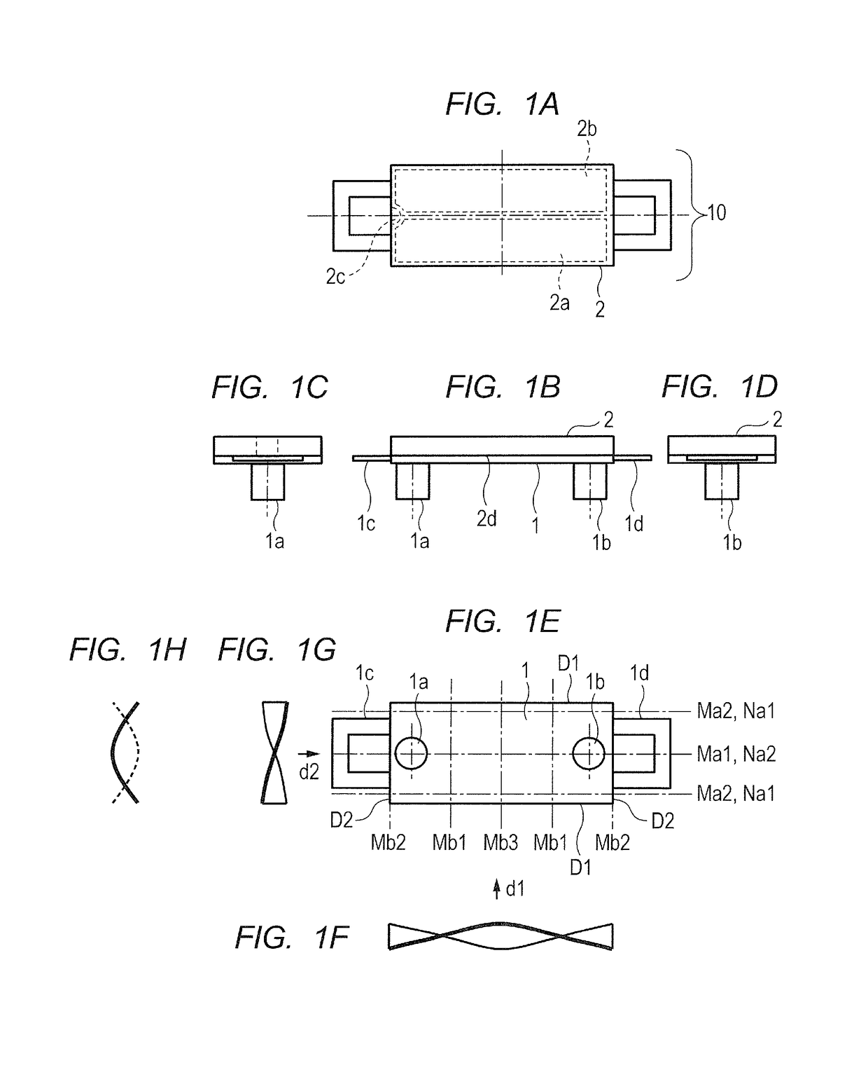
[0049]Now, a first embodiment for carrying out the present invention is described referring to the drawings. FIG. 1A to FIG. 1H are diagrams for illustrating a configuration of a vibration wave motor of the first embodiment according to the present invention. FIG. 1A is a plan view, FIG. 1B is a front view, FIG. 1C and FIG. 1D are side views, and FIG. 1E is a bottom view. In FIG. 1A to FIG. 1H, two projections 1a and 1b are provided on one rectangular surface of a vibrating plate 1. The projections 1a and 1b are integrally molded with the vibrating plate 1 through drawing or formed by bonding separate components on the vibrating plate 1.

[0050]A piezoelectric device 2 that vibrates at high frequency is bonded onto a surface of the vibrating plate 1 on a side opposite to the side where the projections 1a and 1b are provided. The piezoelectric device 2 includes two regions 2a and 2b obtained by polarization in the same direction. The region 2a is allocated to an A-phase, whereas the re...

second embodiment

[0078]Now, a second embodiment for carrying out the present invention is described referring to the drawings. FIG. 8A to FIG. 8H are diagrams for illustrating a configuration of a vibration wave motor 20 according to the second embodiment, and are equivalent to FIG. 1A to FIG. 1H for illustrating the first embodiment. As illustrated in FIG. 8A to FIG. 8H, the vibration wave motor 20 includes a vibrating plate 11, a piezoelectric device 12, and coupling portions 11c and 11d, and therefore has the same configuration as that of the first embodiment illustrated in FIG. 1A to FIG. 1H.

[0079]The piezoelectric device 12 includes regions obtained by polarization, similar to those illustrated in FIG. 1A to FIG. 1H of the first embodiment. The first embodiment and the second embodiment differ from each other in the following point. Specifically, the two projections 1a and 1b are provided in the first embodiment, whereas a single projection 11a is provided in the second embodiment. The vibratin...

third embodiment

[0091]Now, a third embodiment for carrying out the present invention is described. FIG. 10A to FIG. 10H are diagrams for illustrating a configuration of a vibration wave motor 30 according to the third embodiment, and are equivalent to FIG. 1A to FIG. 1H of the first embodiment. As illustrated in FIG. 10A to FIG. 10H, the vibration wave motor 30 includes a vibrating plate 21, a piezoelectric device 22, and coupling portions 21c and 21d, and therefore has the same configuration as that of the first embodiment illustrated in FIG. 1A to FIG. 1H.

[0092]The piezoelectric device 22 includes regions obtained by polarization, similar to those illustrated in FIG. 1A to FIG. 1H of the first embodiment. The vibrating plate 21, the piezoelectric device 22, and projections 21a and 21b form the vibration wave motor 30. By applying the AC voltages from the power feeding unit (not shown) with the phase difference between the A-phase and the B-phase being freely changed, the vibration can be caused.

[...


PUM


Abstract

A vibration wave motor includes a vibrating plate having a rectangular surface; a piezoelectric device bonded to the vibrating plate, and configured to vibrate at high frequency; and a projection provided on the vibrating plate or the piezoelectric device. In the vibration wave motor, a natural vibration mode, which has a resonant frequency equal to or adjacent to a resonant frequency of torsional vibration in a natural vibration mode under a state in which the vibrating plate, the piezoelectric device, and the projection are integrated, is a natural vibration mode of bending vibration in a direction parallel to or orthogonal to a torsion center axis of the torsional vibration in the natural vibration mode. The projection is provided at a position closer to an antinode than to a node, which are in the direction orthogonal to the torsion center axis of the torsional vibration in the natural vibration mode.

Description

BACKGROUND OF THE INVENTION[0001]Field of the Invention[0002]The present invention relates to a vibration wave motor, and more particularly, to a vibration wave motor for linear drive including a plate-like elastic body. The present invention also relates to a driving apparatus using the vibration wave motor and to a driving apparatus including the vibration wave motor described above.[0003]Description of the Related Art[0004]Hitherto, vibration wave motors with features of small-size and lightweight, high-speed drive, and quiet drive have been employed for lens barrels of image pickup apparatus. Among the vibration wave motors, the following vibration wave motor is described in Japanese Patent Application Laid-Open No. 2012-16107 as a vibration wave motor for linear drive.[0005]FIG. 20A to FIG. 20G are diagrams for illustrating a configuration of a related-art vibration wave motor 600. FIG. 20A is a plan view, FIG. 20B is a front view, FIG. 20C and FIG. 20D are side views, and FIG....

Claims


Application Information

Patent Timeline
Patent Type & Authority Patents(United States)
IPC IPC(8): H01L41/09H02N2/00H02N2/02
CPCH02N2/026H02N2/001
Inventor NISHITANI, HITOSHININOMIYA, SHUNSUKE
Owner CANON KK
Why Eureka
Try Eureka