Vibration wave motor and driving apparatus using the vibration wave motor
a technology of vibration wave motor and driving apparatus, which is applied in the direction of piezoelectric/electrostrictive/magnetostrictive devices, piezoelectric/electrostriction/magnetostriction machines, electrical apparatus, etc., can solve the problem of insufficient amplitude in the perpendicular direction (i) and the inability to obtain thrust force, so as to reduce the size of the vibration wave motor and the effect of downsizing the driving apparatus
- Summary
- Abstract
- Description
- Claims
- Application Information
AI Technical Summary
Benefits of technology
Problems solved by technology
Method used
Image
Examples
first embodiment
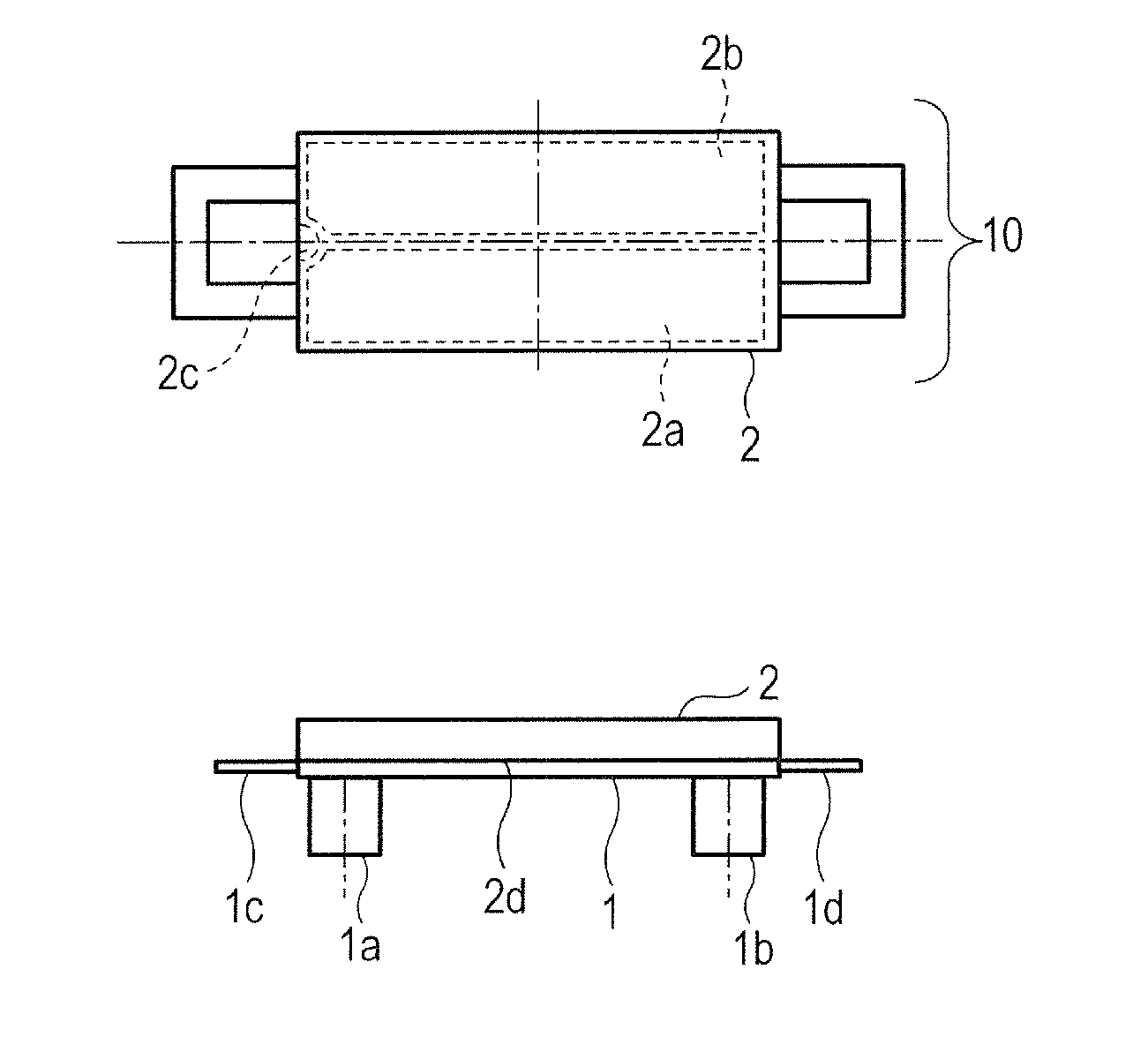
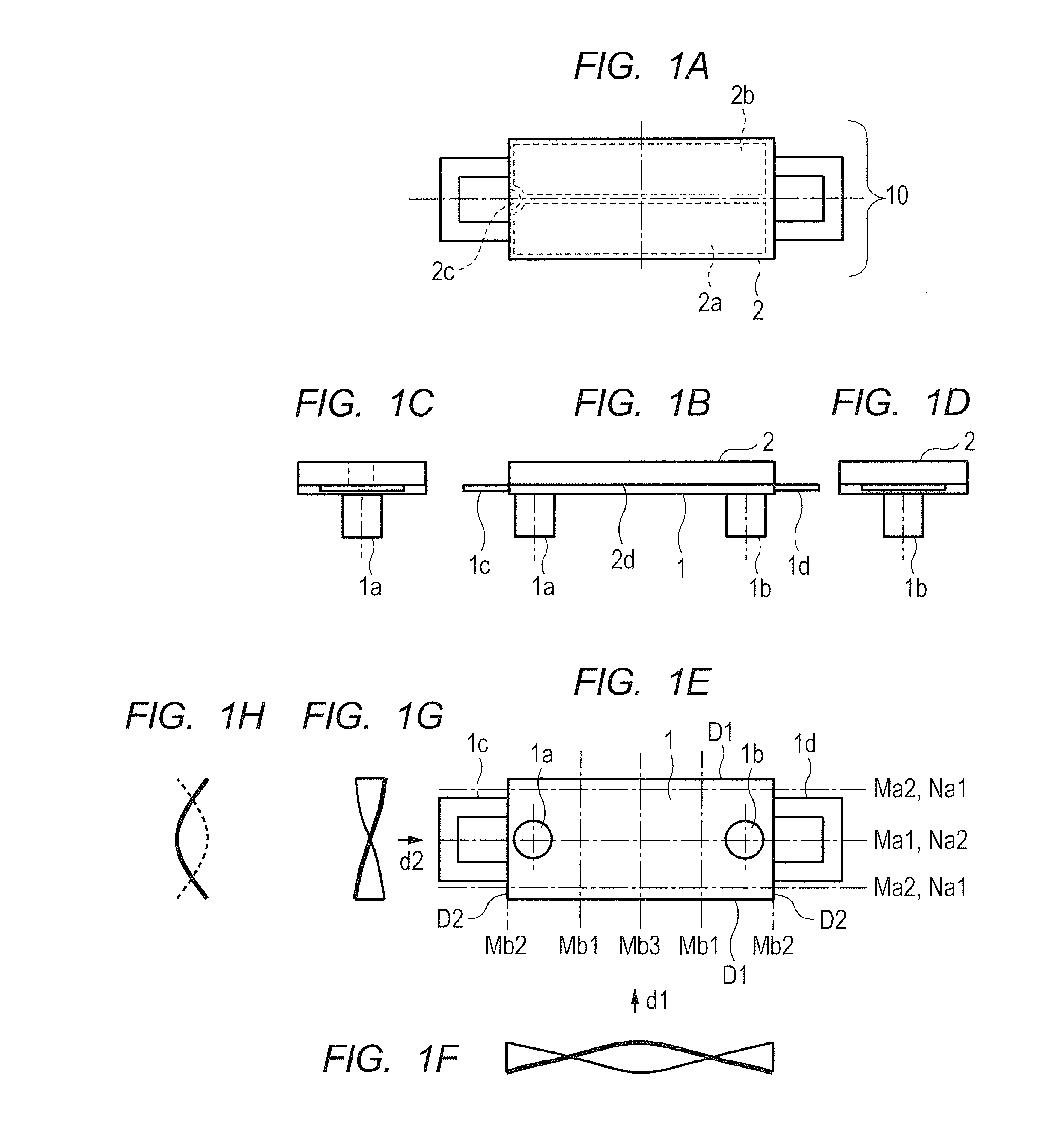
[0049]Now, a first embodiment for carrying out the present invention is described referring to the drawings. FIG. 1A to FIG. 1H are diagrams for illustrating a configuration of a vibration wave motor of the first embodiment according to the present invention. FIG. 1A is a plan view, FIG. 1B is a front view, FIG. 1C and FIG. 1D are side views, and FIG. 1E is a bottom view. In FIG. 1A to FIG. 1H, two projections 1a and 1b are provided on one rectangular surface of a vibrating plate 1. The projections 1a and 1b are integrally molded with the vibrating plate 1 through drawing or formed by bonding separate components on the vibrating plate 1.
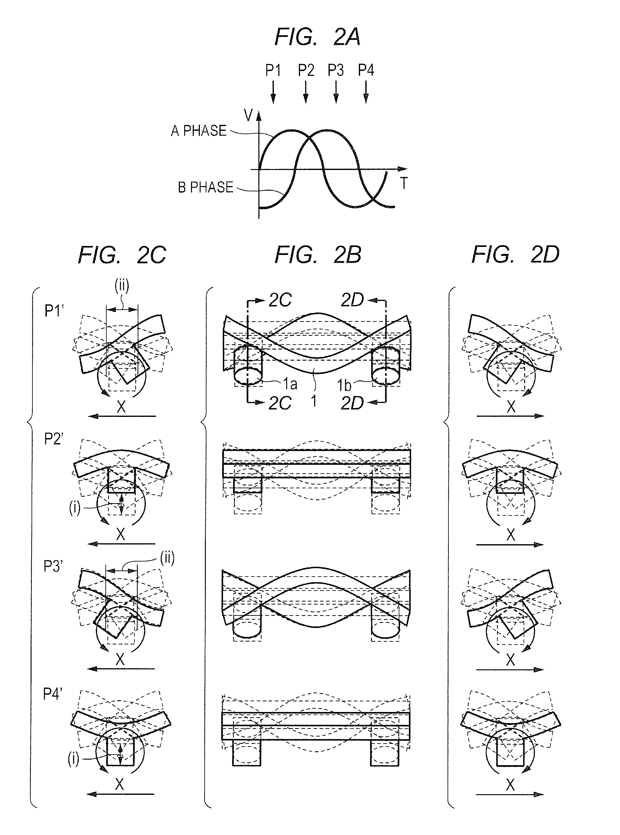
[0050]A piezoelectric device 2 that vibrates at high frequency is bonded onto a surface of the vibrating plate 1 on a side opposite to the side where the projections 1a and 1b are provided. The piezoelectric device 2 includes two regions 2a and 2b obtained by polarization in the same direction. The region 2a is allocated to an A-phase, whereas the re...
second embodiment
[0078]Now, a second embodiment for carrying out the present invention is described referring to the drawings. FIG. 8A to FIG. 8H are diagrams for illustrating a configuration of a vibration wave motor 20 according to the second embodiment, and are equivalent to FIG. 1A to FIG. 1H for illustrating the first embodiment. As illustrated in FIG. 8A to FIG. 8H, the vibration wave motor 20 includes a vibrating plate 11, a piezoelectric device 12, and coupling portions 11c and 11d, and therefore has the same configuration as that of the first embodiment illustrated in FIG. 1A to FIG. 1H.
[0079]The piezoelectric device 12 includes regions obtained by polarization, similar to those illustrated in FIG. 1A to FIG. 1H of the first embodiment. The first embodiment and the second embodiment differ from each other in the following point. Specifically, the two projections 1a and 1b are provided in the first embodiment, whereas a single projection 11a is provided in the second embodiment. The vibratin...
third embodiment
[0091]Now, a third embodiment for carrying out the present invention is described. FIG. 10A to FIG. 10H are diagrams for illustrating a configuration of a vibration wave motor 30 according to the third embodiment, and are equivalent to FIG. 1A to FIG. 1H of the first embodiment. As illustrated in FIG. 10A to FIG. 10H, the vibration wave motor 30 includes a vibrating plate 21, a piezoelectric device 22, and coupling portions 21c and 21d, and therefore has the same configuration as that of the first embodiment illustrated in FIG. 1A to FIG. 1H.
[0092]The piezoelectric device 22 includes regions obtained by polarization, similar to those illustrated in FIG. 1A to FIG. 1H of the first embodiment. The vibrating plate 21, the piezoelectric device 22, and projections 21a and 21b form the vibration wave motor 30. By applying the AC voltages from the power feeding unit (not shown) with the phase difference between the A-phase and the B-phase being freely changed, the vibration can be caused.
[...
PUM
 Abstract
Description
Claims
Application Information
 - R&D
- Intellectual Property
- Life Sciences
- Materials
- Tech Scout
- Unparalleled Data Quality
- Higher Quality Content
- 60% Fewer Hallucinations
Browse by: Latest US Patents, China's latest patents, Technical Efficacy Thesaurus, Application Domain, Technology Topic, Popular Technical Reports.
© 2025 PatSnap. All rights reserved.Legal|Privacy policy|Modern Slavery Act Transparency Statement|Sitemap|About US| Contact US: help@patsnap.com


