Method for determining a pressure/volume characteristic curve of a wheel brake

a technology of pressure/volume characteristic curve and wheel brake, which is applied in the direction of braking system, automatic initiation, transportation and packaging, etc., can solve the problems of inability to obtain a sufficient braking effect via one wheel to stop the vehicle reliably, and the execution of this method is considered disadvantageous

Active Publication Date: 2019-01-08
CONTINENTAL TEVES AG & CO OHG
View PDF28 Cites 2 Cited by
  • Summary
  • Abstract
  • Description
  • Claims
  • Application Information

AI Technical Summary

Benefits of technology

[0007]An aspect of the invention provides the advantage that the determination of the pressure / volume characteristic curves of the individual wheel brakes can be carried out during normal service braking operations since as a result of at least two wheel brakes being activated by the pressure supply device, the motor vehicle can be braked in a sufficiently stable fashion given a suitable selection of the wheel brakes.
[0016]For a pressure value, the capacity for each wheel brake is preferably obtained from the associated, determined pressure medium volumes on the basis of a linear equation system. If the number of different groups of wheel brakes whose group capacity has been measured is larger than the number of wheel brakes, this equation system is overdetermined. The overdetermined equation system is advantageously solved approximately according to the method of the least mean squares. This makes the method more robust with respect to measuring errors.
[0017]In the event of a group of wheel brakes comprising precisely two wheel brakes, it is preferred if the group comprises two wheel brakes which are located diagonally opposite one another or the two front wheel brakes. Then, during braking the wheel brakes which are located diagonally opposite one another or the two front wheel brakes are activated, as a result of which the vehicle can be braked in a stable fashion even when only two wheel brakes are activated.
[0019]A method according to an aspect of the invention for obtaining the pressure / volume characteristic curves of the wheel brakes, i.e. the corresponding activation of the wheel brakes, in particular groups of wheel brakes, by the pressure supply device is preferably aborted as soon as a brake pressure control function is requested or becomes necessary. A method according to the invention is advantageously aborted immediately if an anti-lock brake control process or a vehicle movement dynamics control process is initiated or activated. This ensures the safety and vehicle stability during the braking operation.
[0026]The pressure supply device is preferably formed by a piston-cylinder arrangement whose piston can be activated by an electromechanical actuator. It is therefore possible for the pressure medium volume which is output by the pressure supply device to be easily determined by means of a travel-detecting device or a position-detecting device, particularly preferably a rotor position-detecting device which detects a variable which characterizes a position of the piston.
[0028]The brake system preferably comprises a pedal travel simulator which gives the vehicle driver a pleasant braking pedal sensation in the “brake-by-wire” operating mode. The pedal travel simulator is particularly preferably of hydraulic design and is or can be connected to the master brake cylinder. The pedal travel simulator is advantageously designed such that it can be switched on and off by means of a simulator release valve.

Problems solved by technology

It is felt to be disadvantageous here that this method can be carried out only to a chronologically limited extent, specifically when the vehicle is stationary.
Furthermore, the execution of this method is felt to be disadvantageous both when the brake pedal is activated and when the brake pedal is unactivated.
In the case of an activated brake pedal, it is, under certain circumstances, impossible to obtain a sufficient braking effect via one wheel to stop the vehicle reliably.
In the event of the brake system being currently serviced, the servicing personnel could be injured by the clamping force at the wheel brake in the case of a brake pedal which is unactivated.

Method used


Image

  • Method for determining a pressure/volume characteristic curve of a wheel brake
  • Method for determining a pressure/volume characteristic curve of a wheel brake

Examples


Embodiment Construction

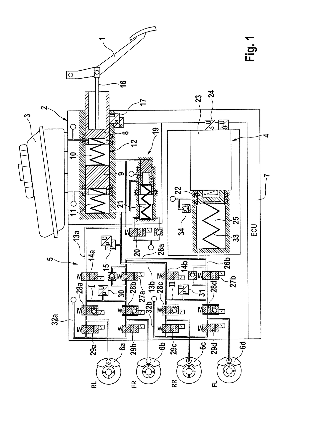
[0033]FIG. 1 is a schematic illustration of an exemplary brake system for carrying out a method according to the invention. The brake system comprises an activation device 2 which can be activated by a vehicle driver by means of an activation pedal or brake pedal 1, a pressure medium reservoir container 3 which is assigned to the activation device 2, an electrically controllable pressure supply device 4, an electrically controllable pressure modulation device 5, to whose output terminals wheel brakes 6a-6d of a motor vehicle (not illustrated) are connected, and an electronic open-loop and closed-loop control unit 7 (ECU: electronic control unit) which serves to process sensor signals and to actuate the electrically controllable components.

[0034]The actuation device 2 comprises a dual-circuit master brake cylinder or tandem master cylinder 12 with two pistons 8, 9 which are arranged one behind the other in a (master brake cylinder) housing and which bound hydraulic pressure chambers ...


PUM


Abstract

Method and system for determining a pressure / volume characteristic curve of a wheel brake in a motor vehicle brake system having an electrically controllable pressure supply device connected hydraulically to wheel brakes and can output a pressure medium volume for activating the wheel brakes. The pressure medium volume which is output by the pressure supply device can be determined. An electrically actuable inlet valve per wheel brake disconnects the connection between the wheel brake and the pressure supply device. During one or more service brake operations of the motor vehicle wheel brakes are activated by the pressure supply device, the pressure medium volume output by the pressure supply device in order to activate the wheel brakes is determined and the pressure / volume characteristic curves of the wheel brakes are determined on the basis of pressure medium volumes output by the pressure supply device during one or more service braking operations are determined.

Description

CROSS REFERENCE TO RELATED APPLICATIONS[0001]This application is the U.S. National Phase Application of PCT / EP2013 / 054058, filed Feb. 28, 2013, which claims priority to German Patent Application No. 10 2012 203 495.1, filed Mar. 6, 2012 and German Patent Application No. 10 2013 203 189.0, filed Feb. 27, 2013, the contents of such applications being incorporated by reference herein.FIELD OF THE INVENTION[0002]The invention relates to a method for determining a pressure / volume characteristic curve of a wheel brake in a brake system for motor vehicles and to a brake system.BACKGROUND OF THE INVENTION[0003]In motor vehicle engineering, “brake-by-wire” brake systems are becoming ever more widespread. Such brake systems often comprise not only a master brake cylinder which can be activated by the vehicle driver but also an electrically controllable pressure supply device by means of which the wheel brakes or the master brake cylinder is activated in the “brake-by-wire” operating mode. In ...

Claims


Application Information

Patent Timeline
Patent Type & Authority Patents(United States)
IPC IPC(8): B60T8/172B60T8/48B60T8/40B60T17/02B60T13/74B60T13/68B60T13/66B60T13/14B60T7/04B60W30/14B60T17/22B60T13/12B60T8/50B60T7/12B60T8/36B60T8/32B60T8/17B60T8/00
CPCB60T8/172B60T7/12B60T8/00B60T8/17B60T8/32B60T8/36B60T8/40B60T8/4081B60T8/48B60T8/50B60T13/12B60T13/14B60T13/146B60T13/662B60T13/686B60T13/745B60T17/02B60T17/22B60W30/14B60T7/042B60T2270/82B60T2270/14
Inventor BILLER, HARALD
Owner CONTINENTAL TEVES AG & CO OHG
Why Eureka
Try Eureka