
Spring applied, hydraulically released wheel-mount brake having improved stationary disc support

a technology of hydraulic release and wheel-mounted brake, which is applied in the direction of hydraulically actuated brakes, brake discs, mechanical equipment, etc., can solve the problems of limited available space for brakes, inability to change or increase the available space, and high cost and efficiency, so as to reduce machining operations and minimal capital investment

Active Publication Date: 2019-01-08
LAMBERT BRAKE
View PDF4 Cites 0 Cited by
  • Summary
  • Abstract
  • Description
  • Claims
  • Application Information

AI Technical Summary

Benefits of technology

The present invention provides a spring applied, hydraulically released brake that reduces machining operations and requires minimal capital investment. The brake is designed to support the stationary discs in a more compact and effective manner, making assembly easier.

Problems solved by technology

This is expensive and inefficient.
Brakes for these vehicles also must be compact with regard to space as available space for the brakes is limited.
When considering replacement brakes for these vehicles, the available space cannot be changed or increased.

Method used


Image

  • Spring applied, hydraulically released wheel-mount brake having improved stationary disc support
  • Spring applied, hydraulically released wheel-mount brake having improved stationary disc support
  • Spring applied, hydraulically released wheel-mount brake having improved stationary disc support

Examples


Embodiment Construction

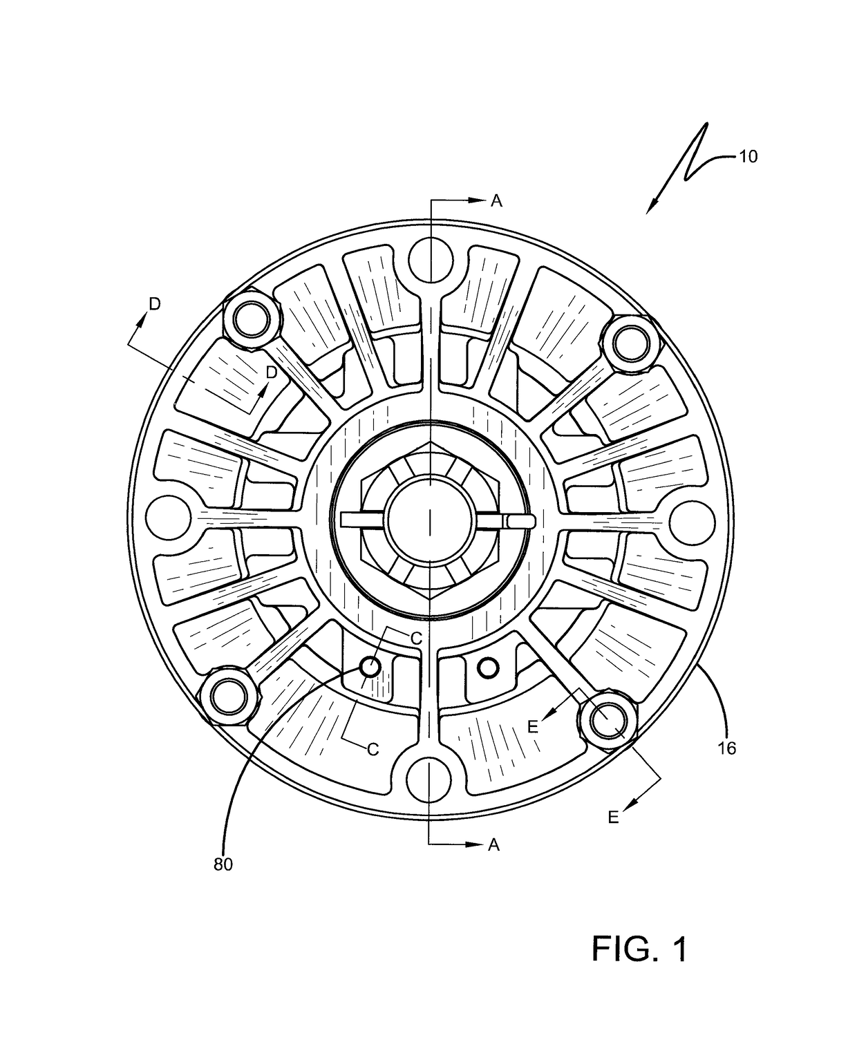
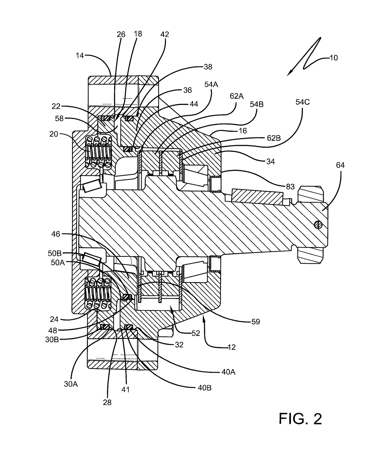
[0027]A brake according to the concepts of the present invention is generally indicated by the numeral 10. Brake 10 includes a housing, generally indicated by the numeral 12, which carries and protects components of brake 10 and locates it in operative relation to a conventional wheel. Housing 12 is formed from two main pieces—a first housing portion 14 that is capable of receiving a second housing portion 16—that can be secured in respective position with each other using one or more fasteners, such as bolt 17 and nut 19 (FIG. 7). As will be described further herein, second portion 16 includes a protrusion that fits into a bore of first portion 14.

[0028]First housing portion 14, which can also be described as a power plate 14, houses a spring applied, hydraulically released (SAHR) assembly, which includes a piston 18 and a plurality of springs 20 capable of acting on piston 18. Piston 18 includes a body portion 22 including one or more spring housings 24 to receive springs 20 there...


PUM


Abstract

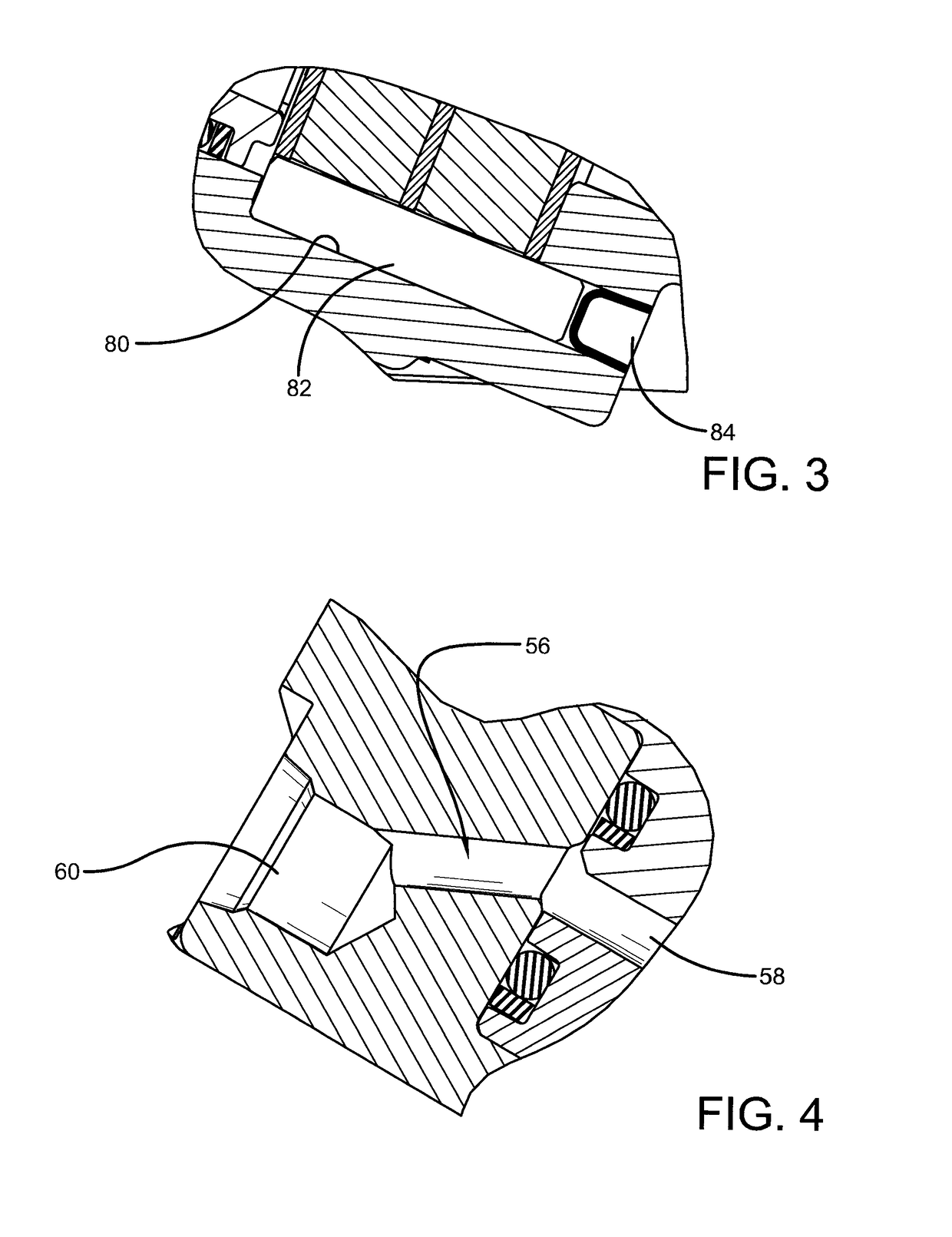
A brake (10) includes a housing (12) formed from a first housing portion (14) capable of receiving a second housing portion (16). The first housing portion (14) houses a piston (18) and a plurality of springs (20), and the second housing portion (16) houses an alternating arrangement of discs (52) for enacting a braking function. The second housing portion (16) further includes torque pin holes (80) for receiving torque pins (82) therein. Each torque pin (82) is secured with a plug (84) to secure stationary discs (54A, 54B, 54C) in place. The stationary discs (54A, 54B, 54C) have extending ears (74) positioned between torque pin grooves (76), which further receive the torque pins (82).

Description

CROSS REFERENCE TO RELATED APPLICATION[0001]This application claims the benefit of U.S. Provisional Application No. 62 / 337,957, filed May 18, 2016, which is incorporated herein by reference.TECHNICAL FIELD[0002]This invention relates to a spring applied, hydraulically released brake. More particularly, this invention relates to a spring applied, hydraulically released brake that includes an improved stationary disc support.BACKGROUND[0003]Scissor lift and telehandler vehicles are known to use spring applied, hydraulically released brakes as a parking brake. These vehicles generally use multi-disc parking brakes located at the wheels of the vehicle. These brakes generally utilize hydraulic fluid to create hydraulic pressure in order to release the brake. The source of this hydraulic pressure is usually from vehicle hydraulics, since these vehicles generally include a hydraulic system. Brakes for these vehicles are generally built using several sand cast iron components, which are the...

Claims


Application Information

Patent Timeline
Patent Type & Authority Patents(United States)
IPC IPC(8): F16D55/40F16D65/12F16D55/36F16D65/18F16D55/00F16D65/02F16D121/06F16D121/12F16D121/14
CPCF16D55/40F16D55/36F16D65/12F16D65/186F16D2250/0084F16D2065/1372F16D2121/06F16D2121/12F16D2121/14F16D2055/0033
Inventor DENNIS, BRIAN P.LEONARD, NANCY L.BALDEOSINGH, HOWARD H.
Owner LAMBERT BRAKE
Learn More