Fluid control measuring and controlling device

a technology of measuring and controlling device and fluid flow, which is applied in the direction of program control, instruments, heating types, etc., can solve the problems of prohibitive cost of measuring low fluid flow, inability to support accurate measuring functionality of fluid flow, and high cost of measuring and regulating fluid flow, etc., to achieve the effect of optimizing energy consumption

Active Publication Date: 2019-01-08
BEST TECH
View PDF35 Cites 13 Cited by
  • Summary
  • Abstract
  • Description
  • Claims
  • Application Information

AI Technical Summary

Benefits of technology

[0010]In another aspect, the variable opening comprises a plurality of additional openings that are arranged in parallel. In yet another aspect, at least one of the nested elements is 10 inches in diameter D and a neighboring nested element is 3.5 inches in diameter d, further wherein a ratio D:d is about 10:3.5 and scalable.
[0013]The fluid device may further include a regain section defined by a tear drop nacelle defining at least a portion of the flow pathway downstream of the orifice plate, wherein the tear 15 drop nacelle reduces losses from increased velocity Venturi or Bernoulli effects imparted on the fluid flow upstream of the nacelle. In some embodiments, the flow device includes a hollow outer shaft extending from the outer assembly and an inner shaft extending from the inner assembly through the hollow outer shaft, wherein the inner and outer shafts are operatively connected with the actuator assembly. The actuator assembly may comprise a first actuator operatively coupled to the hollow outer shaft and a second actuator operatively coupled to the inner shaft. Furthermore, the first and second actuators may be collinear and ganged together to enable measurability and controllability over a wide flow range. In other embodiments, the first and second actuators are mounted in parallel or on opposite sides of the flow device.
[0037]The method may further include the step of checking if the predetermined target flow F has changed, wherein if the target flow F has not changed and Q≠F, signaling an actuator to adjust the control element to the new setting. Further, the method comprises providing a plurality of control elements in series or in parallel in the flow pathway, measuring the pressure differential ΔP across the plurality of control elements, and determining the magnification coefficient MF based on the variable opening area Ao of a critical control element in the plurality of control elements. Still further, the method includes enhancing or magnifying the measured pressure differential ΔP across the control element and calculating the flow rate Q based on the enhanced or magnified pressure differential ΔP along with the magnification coefficient to achieve a precise flow rate Q. In some embodiments, the control element is a thin blade control element and the pressure differential ΔP is measured across the blade to enhance readings.
[0039]In yet another embodiment of the present disclosure, a central control system for use in a heating, ventilation, and air conditioning (HVAC) system is provided. The central controls system includes a processor and a memory communicatively coupled with and readable by the processor and having stored therein processor-readable instructions that, when executed by the processor, cause the processor to receive data from a plurality of flow controllers, wherein each of the plurality of flow controllers operates a flow device positioned remotely from the central controls system. The data may comprise a pressure differential measured at each of the plurality of flow controllers, a variable opening area of a flow pathway provided by each flow device, a magnification coefficient MF based on square of a ratio of the variable opening area to a flow pathway area at each of the plurality of flow devices, wherein the magnification coefficient MF is a non-constant coefficient and 0≤MF≤1, and / or a flow rate based on the pressure differential and the magnification coefficient. The central controller may adjust fan parameters such that 1) all remote controllers are satisfied and 2) at least one remote control device is wide open, thus optimizing energy consumption. The central control system may further send operation parameters to each of the plurality of flow controllers independently. If one or more remote controllers is unsatisfied (i.e. wide open and needing more flow), and fan is at maximum, central control may command satisfied or more nearly satisfied controllers to feather back to balance the load, based on degree of dissatisfaction reported by remote controllers.

Problems solved by technology

Measuring and regulating fluid flows, such as air or water flow, is common, but typically expensive, particularly for low fluid flows.
In many cases, costs for measuring low fluid flows may be prohibitive and not commercially viable.
Further, current flow measurement devices provide limited turndown ratio, typically less than 10:1, and therefore do not support accurate measuring functionality for fluid flows.
These low turn down devices create millions of unnecessary part numbers which creates a dysfunctional cumbersome business model.
For instance, typical heating, ventilation, air conditioning (“HVAC”) systems do not perform with accuracy due to the high costs of measuring air flow and limited turndown.
This causes the HVAC systems to consume needless amounts of energy and also hinders their purpose of providing comfort to people in a building.

Method used


Image

  • Fluid control measuring and controlling device
  • Fluid control measuring and controlling device
  • Fluid control measuring and controlling device

Examples


Embodiment Construction

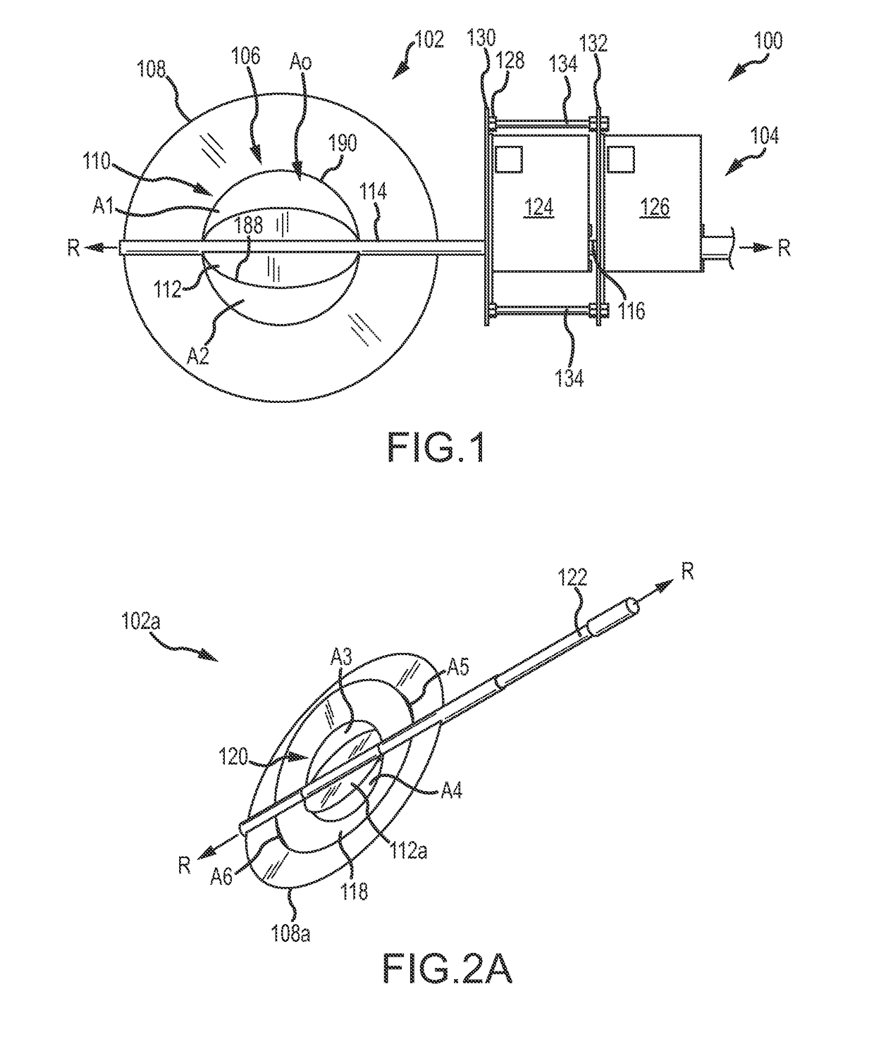
[0078]The present disclosure describes a flow device, also referred to as a fluid control measuring device or a low flow fluid controller (“LFFC”), that offers a high turndown ratio for measuring and regulating various types of fluid flow, such as gaseous or liquid fluid flows having high or low velocity. It is noted that although the term LFFC may be used throughout the application, the flow device is applicable to a variety of fluid flows and is not limited to low flow. The LFFC can be incorporated into a duct, a self-contained heating, ventilation, and air conditioning (“HVAC”) equipment, or any air or fluid discharge or distribution device. Further, the LFFC is a smart device capable of interacting with other devices through a variety of networks, including Bluetooth, WiFi, 3G, 4G, and the like.

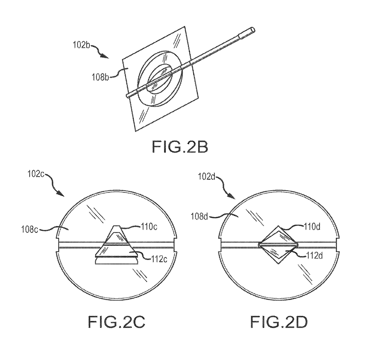
[0079]In some embodiments, the LFFC is a circular plate-like device that includes one or more damper regulators and / or fluid control valves mounted in series and / or parallel in a flow pat...


PUM


Abstract

Systems and methods for measuring and controlling fluid flow comprises an orifice plate defining a variable opening, wherein the orifice plate includes an outer assembly comprising a central opening and an inner assembly extending through the central opening. Another embodiment comprises a plurality of blades disposed parallel to each other, wherein the blades are pivotable along its longitudinal axis and include at least one low-flow blade or partial blade and a plurality of high-flow blades The flow device regulates high and very low volumes of fluid with precision, inexpensively, with superior acoustics, reduced energy, a simpler design, and prevents building infiltration. The high turndown device permits use at lower velocities, thereby reducing noise generation and eliminating need for sound-attenuating liners. The high rangeability device combines several part numbers into fewer parts, thereby streamlining product portfolios. Cost benefits associated with the flow device allow equipment to be scaled back 100:1 rather than legacy 4:1, providing energy savings, fewer product variations, simple and more robust applications. The device meets new and old building fresh air, comfort and energy codes. The flow device can be engineered, selected, and sized without sophisticated software programs.

Description

CROSS-REFERENCE TO RELATED APPLICATIONS[0001]This application is a Continuation-in-Part of U.S. application Ser. No. 14 / 330,941 filed Jul. 14, 2014 entitled “FLUID CONTROL MEASURING DEVICE,” which claims priority to U.S. Provisional Patent Application No. 61 / 872,576 filed Aug. 30, 2013 and entitled “LOW FLOW FLUID CONTROLLER,” and claims priority to U.S. Provisional Patent Application No. 61 / 845,665 filed Jul. 12, 2013 entitled “LOW FLOW DAMPER.” The entire contents of each of these disclosures are hereby incorporated by reference for all purposes, as if fully set forth herein.BACKGROUND OF THE INVENTION[0002]Measuring and regulating fluid flows, such as air or water flow, is common, but typically expensive, particularly for low fluid flows. In many cases, costs for measuring low fluid flows may be prohibitive and not commercially viable. Further, current flow measurement devices provide limited turndown ratio, typically less than 10:1, and therefore do not support accurate measurin...

Claims


Application Information

Patent Timeline
Patent Type & Authority Patents(United States)
IPC IPC(8): F24F11/30G05B19/042G05D7/06F24F110/00F24F110/30
CPCG05B19/042F24F11/30G05D7/0635G05B2219/2614F24F2110/00F24F2110/30F24F11/46F24F11/74
Inventor KARAMANOS, JOHN C.WILLKE, HERBERT
Owner BEST TECH
Why Eureka
Try Eureka