Method of fabricating a composite material blade having internal channels, and a composite material turbine engine blade

a technology of composite materials and turbine engines, which is applied in the direction of machines/engines, weaving, other domestic articles, etc., can solve the problems of not being able to machine internal channels in metal blades that present twisted shapes, and not being able to include internal channels in blades of composite materials, so as to preserve the mechanical integrity of the blade structur

Active Publication Date: 2019-01-15
SN DETUDE & DE CONSTR DE MOTEURS DAVIATION S N E C M A
View PDF11 Cites 3 Cited by
  • Summary
  • Abstract
  • Description
  • Claims
  • Application Information

AI Technical Summary

Benefits of technology

[0016]Thus, by the method of the invention, it is possible to fabricate composite material blades having internal channels, while also preserving the mechanical integrity of the blade structure. In the method of the invention, the channels are formed without spoiling the continuity of reinforcing yarns adjacent to the channels.
[0017]Furthermore, since the sacrificial yarns are included in the reinforcement before the fiber blank is shaped, it is possible to make blades of complex shapes, in particular blades that are of twisted shapes, that also include internal channels.

Problems solved by technology

Nevertheless, machining internal channels in blades of metal material is quite difficult and can only be done on blades presenting shapes that are relatively simple.
In particular, it is not possible to machine internal channels in metal blades that present a twisted shape.
Nevertheless, known blades of composite material do not include internal channels.
Machining internal channels in a blade of composite material can spoil the properties and the strength of the blade.
Drilling one or more channels may in particular lead to certain reinforcing yarns being damaged or even broken, thereby harming the cohesion of the fiber reinforcement (by interrupting the paths along which forces are transmitted, which paths are formed by the reinforcing yarns).

Method used


Image

  • Method of fabricating a composite material blade having internal channels, and a composite material turbine engine blade
  • Method of fabricating a composite material blade having internal channels, and a composite material turbine engine blade

Examples


Embodiment Construction

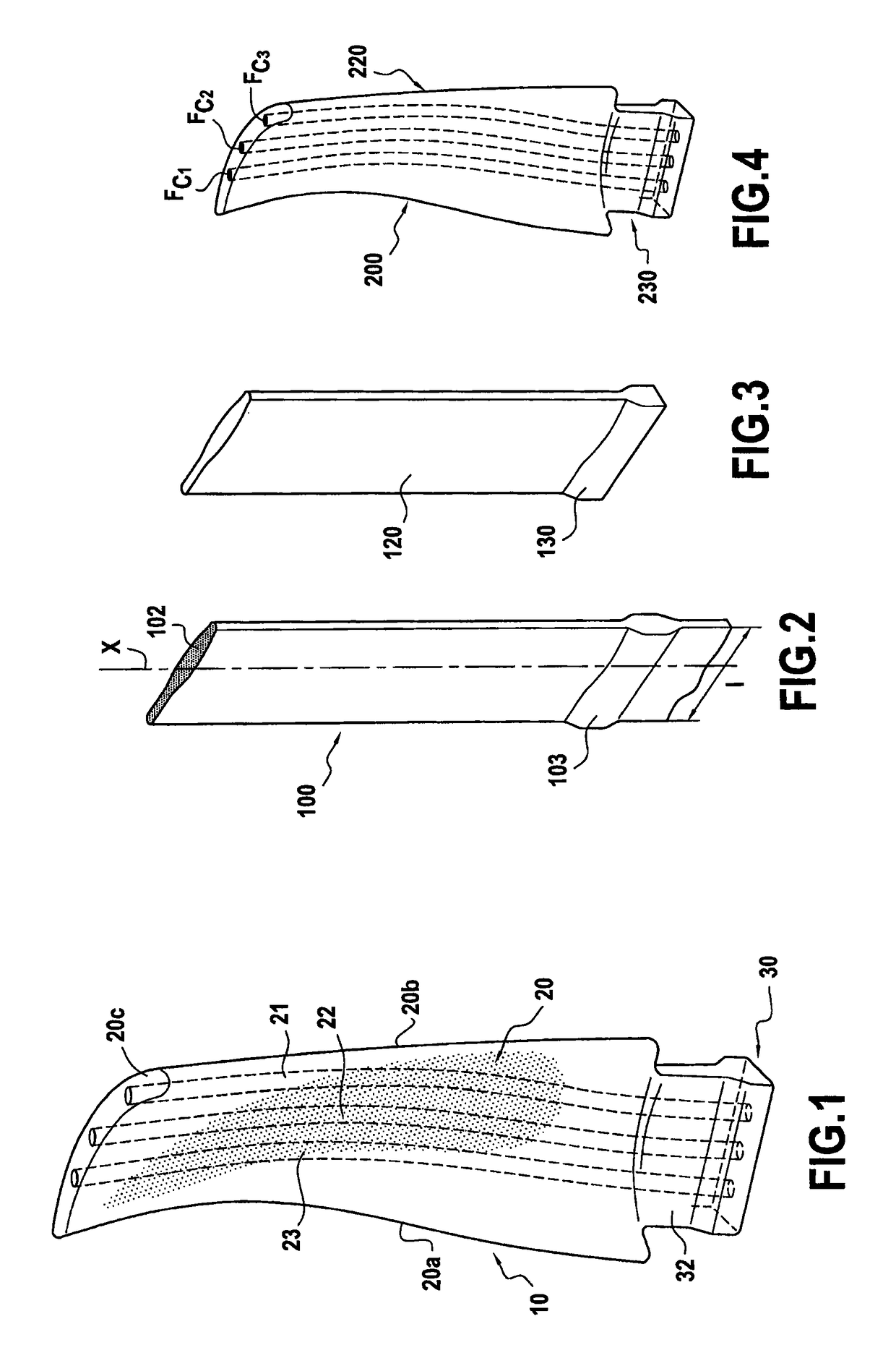
[0034]The invention is applicable to various types of turbine engine blade, in particular compressor blades and turbine blades of various gas turbine spools, e.g. a rotor wheel blade of a low pressure (LP) turbine, such as the blade shown in FIG. 1.

[0035]The blade 10 of FIG. 1 comprises, in well-known manner, an airfoil 20, a root 30 formed by a portion of greater thickness, e.g. having a bulb-shaped section, and extended by a tang 32. The airfoil 20 extends in a longitudinal direction from the root 30 to a tip 20c, and in cross-section it presents a curved profile of thickness that varies between its leading edge 20a and its trailing edge 20b.

[0036]The blade 10 is mounted on a turbine rotor (not shown) by engaging the root 30 in a housing of complementary shape formed in the periphery of the rotor.

[0037]In accordance with the invention, the blade 10 also includes three internal channels 21, 22, and 23 for sucking in air via the root 30 and for blowing it out via the tip 20c of the...


PUM

PropertyMeasurementUnit
temperatureaaaaaaaaaa
weightsaaaaaaaaaa
sizesaaaaaaaaaa

Abstract

A turbine engine blade made of composite material including fiber reinforcement obtained by weaving a first plurality of yarns with a second plurality of yarns, the yarns of the first plurality of yarns being arranged in successive layers and extending in a longitudinal direction of the fiber blank corresponding to a longitudinal direction of the blade, the reinforcement being densified by a matrix. The blade includes one or more internal channels extending in the longitudinal direction of the blade.

Description

BACKGROUND OF THE INVENTION[0001]The invention relates to turbine engine blades having internal channels.[0002]In order to reduce noise and turbulence at the root of a blade, it is known to make internal channels within blades, which channels open out in the vicinities of the root and of the tip of the blade. These internal channels thus form a suck / blow device that draws in (sucks) some of the air level with the root of the blade and exhausts it (blows it out) level with the tip of the blade, thereby enabling a portion of the boundary layer in the proximity of the rotor to be absorbed.[0003]Such blades provided with such suck / blow devices are generally made of a metal material, with the internal channels being hollowed out in the mass of the blade.[0004]Nevertheless, machining internal channels in blades of metal material is quite difficult and can only be done on blades presenting shapes that are relatively simple. In particular, it is not possible to machine internal channels in ...

Claims


Application Information

Patent Timeline
Patent Type & Authority Patents(United States)
IPC IPC(8): F01D5/28B29D99/00F01D5/18B29C70/48B29C70/24B29C33/52D03D25/00B29L31/08
CPCF01D5/282B29C33/52B29C70/24B29C70/48B29D99/0025F01D5/187D03D25/005Y10T29/49337B29L2031/08F05D2260/20F05D2300/21F05D2300/224B29B11/16
Inventor COUPE, DOMINIQUEDAMBRINE, BRUNO JACQUES GERARDMAHIEU, JEAN-NOEL
Owner SN DETUDE & DE CONSTR DE MOTEURS DAVIATION S N E C M A
Why Eureka
Try Eureka