Interlaced Filtration Barrier

a filtration barrier and interlace technology, applied in the field of polymer-based filtration barriers, can solve the problems that the barriers cannot effectively filter out most micron-sized particles and nanoparticles, and achieve the effects of reducing pressure drop, easy scaling up for large-scale production, and high filtration efficiency

Active Publication Date: 2017-01-12
NANO & ADVANCED MATERIALS INST
View PDF0 Cites 3 Cited by
  • Summary
  • Abstract
  • Description
  • Claims
  • Application Information

AI Technical Summary

Benefits of technology

[0009]In one embodiment, the above method further comprises a step of varying the conductivity, viscosity or surface tension of the polymer solution.
[0012]In another exemplary embodiment of the present invention, the nanofibers and microfibers are made from a polymer solution and obtained by varying the conductivity, viscosity or surface tension of the polymer solution.
[0015]The filtration barrier of the present invention provides a number of advantages, for example, the barrier layer includes an interlaced structure of nanofibers and microfibers in which additional support to the filtration barrier can be provided by the interlace without compromising the filtration efficiency of the filtration barrier. The inventors of the present invention appreciate the fact that although filtration efficiency generally increases with increasing nanofiber surface area, and that the surface area increases with decreasing nanofiber diameter, the nanofiber diameter cannot be reduced extensively without limit for a given material. If one needs to further increase the filtration efficiency of the barrier comprising nanofibers at a minimum possible diameter, one has to increase the thickness of the barrier, leading to an increase in pressure drop of the barrier. Therefore, the current invention is the solution to develop a filtration barrier capable of increasing filtration efficiency without causing significant increase in pressure drop.
[0016]The current inventors recognize that nanofibers fabricated via positive voltage and negative voltage electrospinning bear positive and negative electrostatic charges respectively and these charges can be retained for relatively long times. The current inventors also recognize that these charges come from two sources: residual surface charges and excess trapped charges (ETCs) in nanofibers. Unlike surface charges, ETCs do not dissipate easily as ETCs can accumulate at domain boundaries of a polymer. For semicrystalline polymers, charges can be trapped at crystalline / amorphous interface. Electrospun nanofibers made of non-polar polymers generally retain charges for a longer period of time when compared with those made of polar polymers. As most bacteria and viruses are negatively charged, the present solution to this problem is the formation of nanofibrous barriers bearing positive charges. Those charge-bearing barriers can enhance filtration of bacteria and viruses by electrostatic attraction without increasing pressure drop.
[0018]Besides, the filtration barrier has a higher filtration efficiency with lower pressure drop as illustrated in the results discussed below. Further, the barrier layer can be made by one set of solution, of which the conductivity, viscosity, and surface tension are unstable, so that the method of fabricating the barrier layer can be easily scaled up for large-scale production. Last but not least, the barrier layer, when attached to the substrate layer, can maintain its mechanical integrity. Yet, the filtration barrier comprising the substrate layer and the barrier layer is flexible such that roll-to-roll processing is allowed without affecting the mechanical integrity of the barrier layer.

Problems solved by technology

Those barriers cannot effectively filter out most micron-sized particles and nanoparticles while maintaining a low pressure drop.

Method used


Image

  • Interlaced Filtration Barrier
  • Interlaced Filtration Barrier
  • Interlaced Filtration Barrier

Examples


example 1

Filtration Barrier Including Nanofibers Interlaced with Microfibers

1.1 Structure of the Filtration Barrier

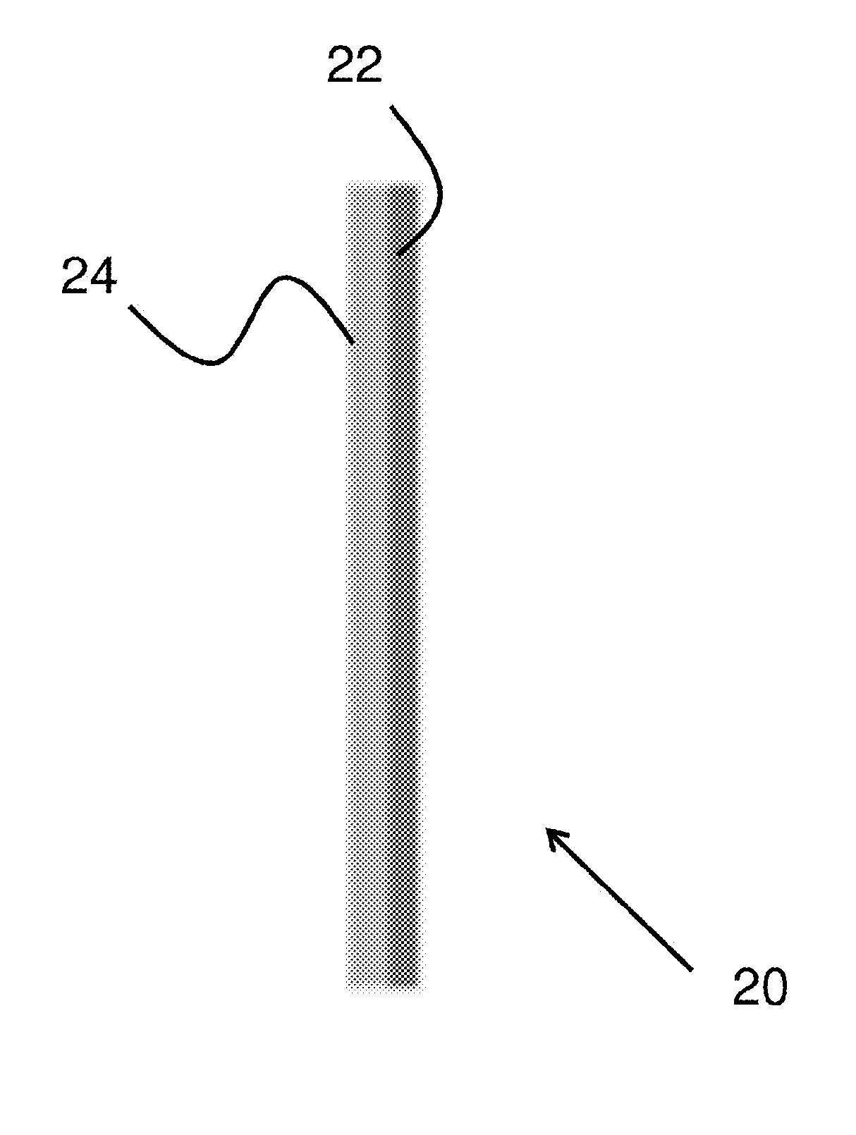
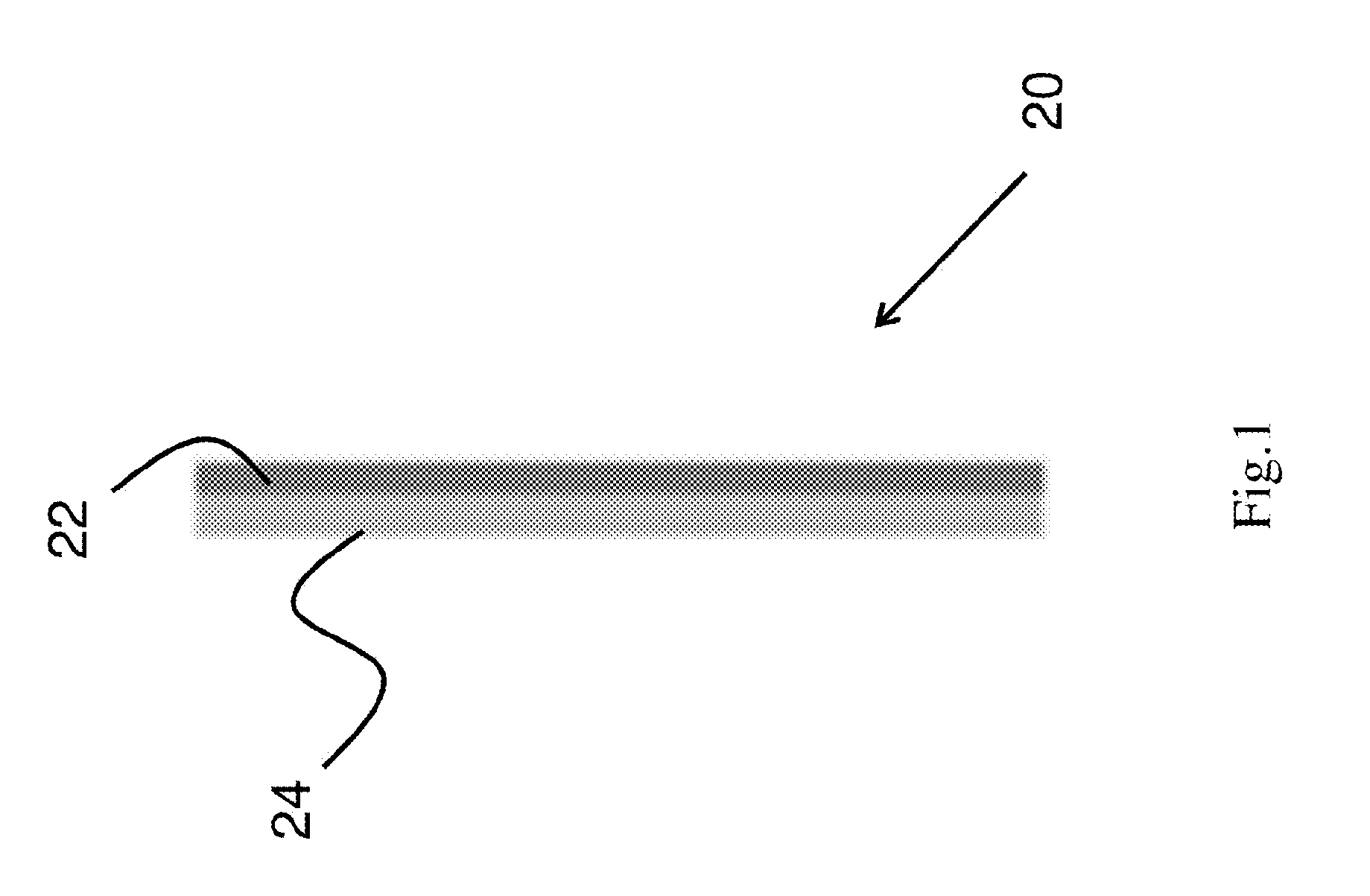
[0029]The first aspect of this invention, as shown in FIG. 1, relates to a filtration barrier 20 including a barrier layer 22 and a substrate layer 24. The barrier layer 22 includes an interlaced structure of polymer-based nanofibers and polymer-based microfibers in which nanofibers and microfibers bear electrostatic charges, whereas the substrate layer 24 is made of polymer-based microfibers. The barrier layer 22 is attached onto the substrate layer 24 via mechanical interlocking and electrostatic attraction.

[0030]In one embodiment, the perimeter of the barrier layer 22 can also be attached onto the perimeter of the substrate layer 24 via ultrasonic welding.

[0031]In one embodiment, the thickness of the barrier layer 22 ranges from 5 to 100 microns whereas the thickness of the substrate layer 24 ranges from 90 to 200 microns.

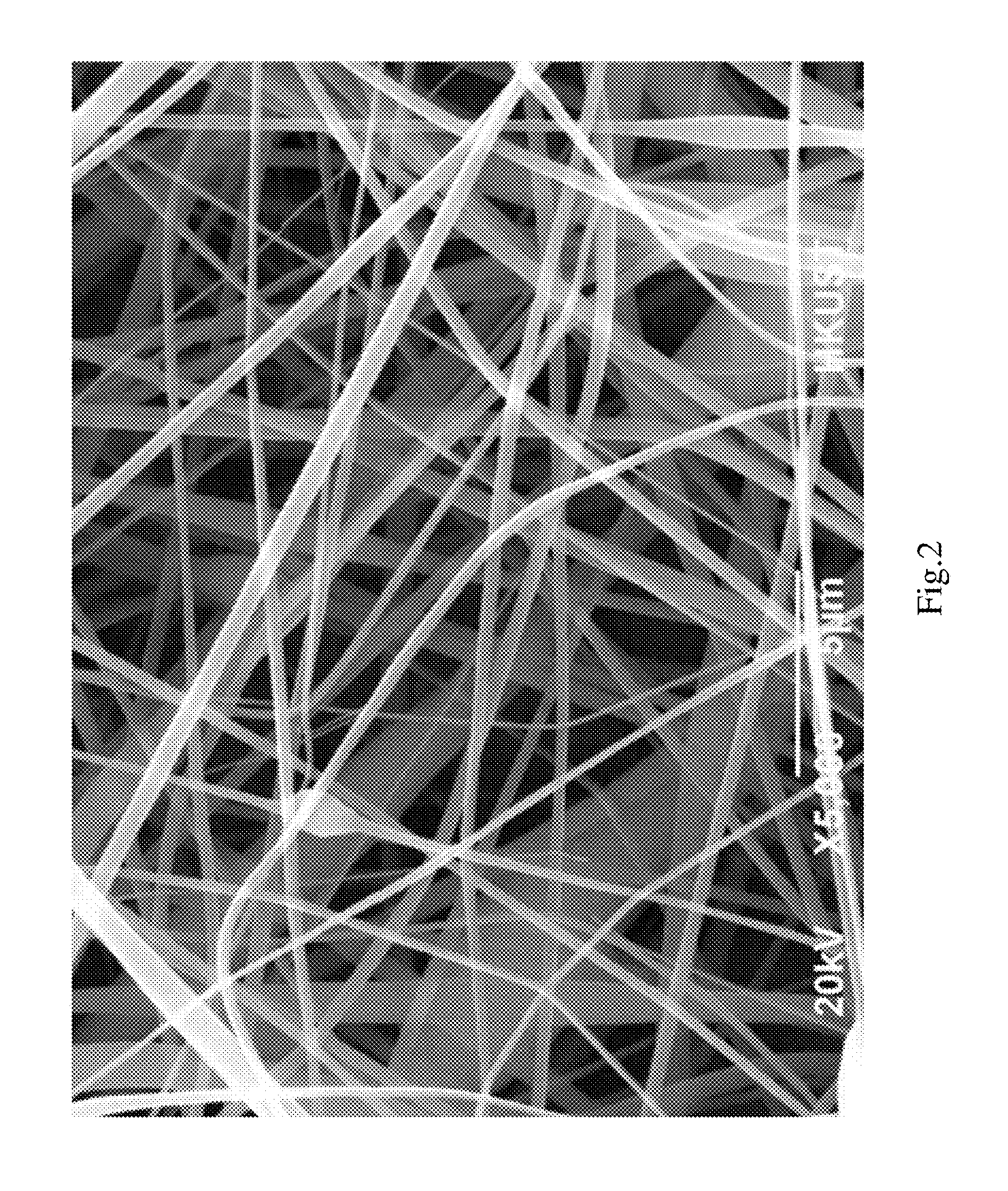
[0032]FIG. 2 shows the morphology of the interlaced st...

example 2

A Filtration Barrier Including a Nanofiber Layer and a Biocide Layer

[0062]In another aspect of this invention, a filtration barrier is described which includes two layers, nanofiber layer and biocide layer, attached to each other. The nanofiber layer is positioned distal to the air-flow direction and includes polymer-based nanofibers bearing positive electrostatic charge. The biocide layer is positioned proximal to the air-flow direction and includes polymer-based nanofibers crosslinked with biocides, in which a first reactive group in the polymer can covalently bind to a second reactive group of the biocide via a crosslinker.

[0063]In one embodiment, the nanofiber layer and biocide layer may further be attached to several fibrous layers.

[0064]On the biocide layer, trap particles can be trapped and kill bacteria can be killed on contact while with the presence of positive charges on the barrier layer, filtration of negatively charged particles such as most bacteria and viruses can be...


PUM

PropertyMeasurementUnit
porosityaaaaaaaaaa
diameteraaaaaaaaaa
diameteraaaaaaaaaa

Abstract

A filtration barrier comprises at least one barrier layer which includes polymeric nanofibers interlaced with microfibers, and at least one substrate layer which includes polymeric microfibers. The filtration barrier can be made by electrospinning process.

Description

FIELD OF INVENTION[0001]This invention relates to a polymer-based filtration barrier and a method of fabricating the same. In particular, the filtration barrier has a barrier layer and a substrate layer.BACKGROUND OF INVENTION[0002]A desirable filtration barrier should possess high filtration efficiency and low pressure drop. Some filtration barriers are made of meltblown fibers having diameters ranging from a few microns to a few tens of microns. Those barriers cannot effectively filter out most micron-sized particles and nanoparticles while maintaining a low pressure drop.SUMMARY OF INVENTION[0003]In the light of the foregoing background, it is an objective of the present invention to provide an alternate filtration barrier.[0004]Accordingly, the present invention, in one aspect, provides a filtration barrier which includes at least one barrier layer and at least one substrate layer. The barrier layer includes a plurality of polymer-based nanofibers interlaced with a plurality of ...

Claims


Application Information

Patent Timeline
Patent Type & Authority Applications(United States)
IPC IPC(8): B01D46/00B01D39/16B29C65/08D01D5/00B29C65/56B01D46/54D01D1/02B29C48/18
CPCB01D46/0032B29L2031/14B01D46/546B01D39/1623D01D1/02D01D5/003D01D5/0076B29C65/565B29C65/08B01D2239/025B01D2239/0435B01D2239/0442B01D2239/0631B01D2239/064B01D2239/065B01D2239/1233B01D46/0028B01D2239/0654B29C48/18B29K2001/00B01D46/62B01D46/0001B01D2239/0645B01D2239/0672B29C65/72B29K2001/12B29K2023/10
Inventor TONG, HO WANGKWOK, SAU KUEN CONNIE
Owner NANO & ADVANCED MATERIALS INST
Why Eureka
Try Eureka