
Centrifugal mass arrangement for the balancing of rotational accelerations of an engine housing

a technology of centrifugal mass and engine housing, which is applied in the direction of engines, machines/engines, springs/dampers, etc., can solve the problems of engine housing vibration, unit and assembly vibration, and achieve the effect of reducing the vibration of the engine housing, suppressing or dampening the rotational oscillation arising from friction during the rolling movemen

Active Publication Date: 2019-01-15
FEV
View PDF15 Cites 0 Cited by
  • Summary
  • Abstract
  • Description
  • Claims
  • Application Information

AI Technical Summary

Benefits of technology

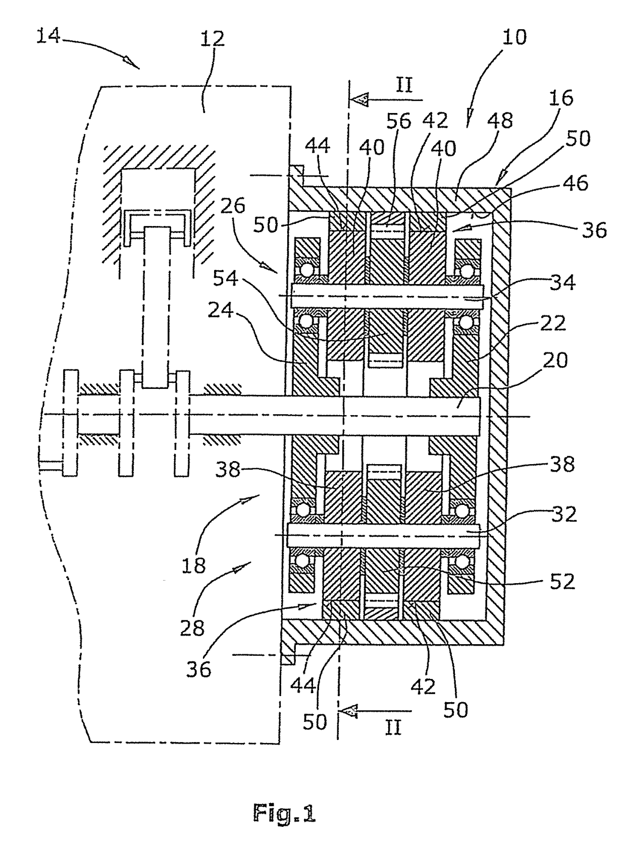
[0011]It is expedient for at least two roller disks, which are fastened to a common shaft, to be arranged on each end of the centrifugal mass carrier. This increases the centrifugal mass.
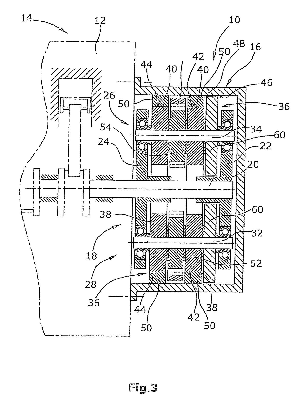
[0013]The greater the centrifugal forces that act on the roller disks during the rotation of the centrifugal mass carrier, the more intensely the roller disks press by way of their circumferential surfaces against the inner side of the housing circumferential wall. In this way, possible slippage between the roller disks and the housing circumferential wall is reduced. In this context, it is furthermore advantageous if the centrifugal mass carrier or the roller disks are coupled by way of a toothing to the housing circumferential wall. This advantageously prevents the occurrence of slippage. The toothing is expediently realized in that, on at least one end of the centrifugal mass carrier, there is situated a gearwheel which is coupled to the at least one roller disk and which is arranged coaxially with respect to the roller disk and which meshes with an internally toothed ring or generally with an internal toothing on the inner side of the circumferential wall of the housing. A gearwheel of said type is preferably, for the compensation of imbalances, arranged on each end of the centrifugal mass carrier. The interaction of each gearwheel with the internal toothing leads to additional running noises. These can be reduced for example through the formation of helical toothings. This is however associated with increased outlay in terms of construction and manufacturing. According to the invention, it is advantageously possible to resort to a standard toothing (that is to say without a helical toothing) because, specifically, the ideal position of the gearwheels relative to the internal toothing with regard to the generation of noise and the transmission of force can be maintained by way of the roller disks even in the presence of high rotational accelerations and rotational speeds, by virtue of the fact that the roller disks are supported on the inner side of the housing circumferential wall and thus prevent the gearwheels from being “pushed into” the internal toothing. Any radial play between the gearwheels and the internal toothing thus does not have any noise-increasing effect, or scarcely has any noise-increasing effect.
[0014]In a further advantageous embodiment of the invention, the centrifugal mass may be further increased in that, in addition to the roller disks, one or more flywheels, which co-rotate with the roller disks, are arranged on each end of the centrifugal mass carrier. The flywheels themselves do not roll on the cylindrical inner side of the housing circumferential wall, but rather rotate “freely”. Improved rolling torque balancing is achieved by way of this additional centrifugal mass.

Problems solved by technology

Engine housings with their automatically rotating or moving parts, elements, units and assemblies are subjected to vibrations owing to linear and rotational accelerations.

Method used


Image

  • Centrifugal mass arrangement for the balancing of rotational accelerations of an engine housing
  • Centrifugal mass arrangement for the balancing of rotational accelerations of an engine housing
  • Centrifugal mass arrangement for the balancing of rotational accelerations of an engine housing

Examples


Embodiment Construction

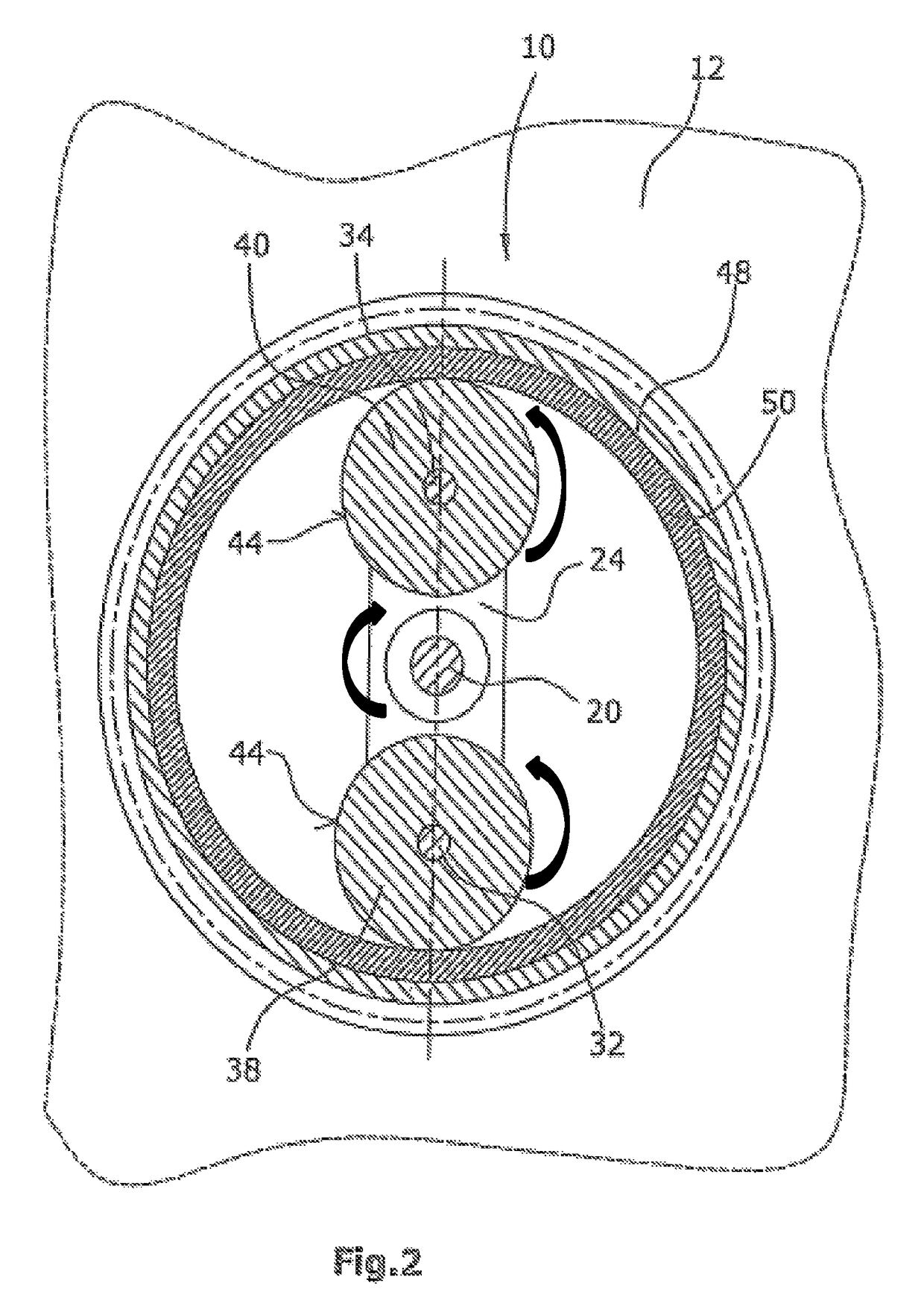
[0021]The exemplary embodiments relate to a centrifugal mass arrangement for coupling to, for example, the crankshaft of a reciprocating-piston engine, which is preferably an internal combustion engine. The centrifugal mass arrangement, which is a multi-component flywheel, which may replace conventional flywheels on reciprocating-piston crankshafts, serves for the balancing of rolling torques which act on the reciprocating-piston engine. The multi-component flywheel has, in this case, a housing in which there is arranged a centrifugal mass carrier with roller disks arranged thereon at each end of the centrifugal mass carrier. The centrifugal mass carrier is fixedly connected to the crankshaft of the reciprocating-piston engine and accordingly rotates in the same rotational direction as the crankshaft. The roller disks roll on the cylindrical inner side of the flywheel housing and, in so doing, rotate in the same direction but oppositely to the direction of rotation of the centrifuga...


PUM


Abstract

The centrifugal mass arrangement for the balancing of rotational accelerations of an engine housing of a reciprocating-piston engine, such as an internal combustion engine, is equipped with a hollow cylindrical housing provided for fastening to the engine housing and has a circumferential wall with an inner side, and with a centrifugal mass carrier arranged rotatably in the housing and coupled to the drive shaft for co-rotation therewith. The centrifugal mass carrier has at least two diametrically oppositely situated ends. A roller disk with a circumferential surface is arranged on each end of the centrifugal mass carrier. Each roller disk is mounted rotatably on the respective end of the centrifugal mass carrier and is supported by the circumferential surface against the inner side of the circumferential wall of the housing and, during rotation of the centrifugal mass carrier, rolls on the inner side of the circumferential wall of the housing.

Description

CROSS-REFERENCE TO RELATED APPLICATIONS[0001]This application claims priority of German Patent Application 10 2015 217 172.8 filed Sep. 9, 2015.FIELD OF THE INVENTION[0002]The invention relates to a centrifugal mass arrangement for the balancing of rotational accelerations of an engine housing, which is in particular the engine housing of a reciprocating-piston engine and preferably of an internal combustion engine.BACKGROUND OF THE INVENTION[0003]Engine housings with their automatically rotating or moving parts, elements, units and assemblies are subjected to vibrations owing to linear and rotational accelerations. In the case of reciprocating-piston engines, it is known for the reciprocating movements to be compensated by way of balancing masses on the crankshaft and / or on balancing shafts. For example, rotating shafts of engine housings are equipped not only with balancing weights but also with flywheels. Upon the start-up of such engines with rotating shafts, the compensating mo...

Claims


Application Information

Patent Timeline
Patent Type & Authority Patents(United States)
IPC IPC(8): F16F15/14F02F7/00F02B75/06
CPCF16F15/1478F02B75/06F16F15/262
Inventor PISCHINGER, MARTIN
Owner FEV
Learn More