Device and method for determining the temperature of a road building material applied by a construction machine, and construction machine comprising such a device

a technology for determining the temperature of road building materials and construction machines, which is applied in the direction of material testing goods, instruments, radiation pyrometry, etc., can solve the problems of high investment, high cost of inability to detect or open high-angle thermal imaging cameras or thermal scanners, etc., to increase the time duration of measurement, and increase the accuracy of measuremen

Active Publication Date: 2019-01-22
MOBA MOBILE AUTOMATION
View PDF9 Cites 1 Cited by
  • Summary
  • Abstract
  • Description
  • Claims
  • Application Information

AI Technical Summary

Benefits of technology

[0021]One advantage of the invention is in the increase of the accuracy of measurement in the area of the asphalt edges and / or roadway edges in that a longer stop of the scanner is caused, i.e. the time duration for a measurement is increased, within said area, e.g. within the area of the lateral asphalt edges. In other words, the speed of the scanner is varied during the movement from the left to the right (or from one side to the other). As compared with a central area, e.g. in the area of the center of the plank, the twisting angle of the scanner in relation to the horizontal is large in said area, and less heat radiation (radiation energy) is reflected onto the sensor by the newly applied road surface. The accuracy of measurement increases as the duration of the measurement at the measuring point increases. In the central area of the roadway, e.g. in the area of the center of the plank, scanning may be performed more quickly, i.e. the stop times of the scanner are shorter since the twisting angle of the scanner in relation to the horizontal is smaller and since, therefore, more heat radiation (radiation energy) is reflected onto the sensor.
[0022]In addition to an increase in the accuracy of measurement, a further advantage of the invention is that, as compared to a constant dwell time, more measuring points, e.g. a smaller distance between measuring points, may be selected within an identical time frame, whereby increased resolution of the measurement system is achieved. Alternatively, the total scan time of a scan process (from one side to the other) may be reduced while the number of measuring points stays the same, as a result of which more scans may be performed and, thus, a higher level of resolution is achieved.
[0023]A dynamic measuring time, e.g. a varying measuring time which increases in a linear, stepwise or exponential manner, for example, of the scanner leads to time savings, e.g. with narrow roads, e.g. a sidewalk, cycle path or the like, since more measurements are possible during the same amount of time as compared to a constant measuring time. As a result, the level of resolution of the measuring system also increases. In the event of broad roads, e.g. motorways, there may actually be a slight increase in the duration of measurement, but the level of accuracy in the area of the asphalt edges and / or roadway edges will be increased, which is not achieved in the event of the measuring time being constant.
[0024]Further embodiments of the present invention provide a device wherein the controller is effective to control, when assembling the device on the construction machine in the area within the placement width (B), the motor based on the assembly position of the device on the construction machine such that the distance between the measuring points on the surface to be measured remains steady.
[0025]In accordance with embodiments, the controller is effective to control the motor additionally based on the assembly angles of the device on the construction machine.
[0026]Thus, a predetermined or preset distance of 25 cm, for example, between two measuring points transverse to the direction of travel of the construction machine is maintained on the surface of the newly applied road building material over the entire placement width, irrespective of the assembly position and the assembly angles of the device. When the assembly position and / or assembly angles of the device are changed, exemplarily when rebuilding a tool at the machine, i.e. the device is shifted in height and / or transverse to the direction of travel of the construction machine and / or the assembly angles of the device are changed, the preset distance of 25 cm, for example, between two measuring points transverse to the direction of travel of the construction machine will be maintained over the placement width even after changing the assembly position and / or the assembly angles.

Problems solved by technology

Disadvantageous with such a temperature sensor is the fact that a thermal-imaging camera or thermal scanner is usually very expensive to buy.
In particular, for smaller building companies such an investment usually cannot be realized due to the high costs.
Furthermore, it is disadvantageous that the detection or opening angles of a thermal-imaging camera or a thermal scanner are highly limited such that, with mounting, or placement, widths in a range of 8 to 12 meters, for example, a correspondingly adapted objective lens has to be applied at the thermal-imaging camera in order to be able to detect the entire placement width of the newly applied road building material.
This, in turn, increases the cost of such a temperature sensor further.
However, this is of particular disadvantage when passing below bridges.
However, the temperature of the newly applied road building material over the entire placement width is not measured directly behind the asphalt plank of the road finishing machine but in a correspondingly large distance to the back edge of the asphalt plank.
When capturing the temperature measuring values by means of the known device, however, the result is not a steady measuring point pattern.
The result here may be a high quantity of data which has to be processed by the control computer.

Method used


Image

  • Device and method for determining the temperature of a road building material applied by a construction machine, and construction machine comprising such a device
  • Device and method for determining the temperature of a road building material applied by a construction machine, and construction machine comprising such a device
  • Device and method for determining the temperature of a road building material applied by a construction machine, and construction machine comprising such a device

Examples


Embodiment Construction

[0064]In the subsequent description of embodiments, same elements or elements of equal effect will be provided with same reference numerals in the appended drawings.

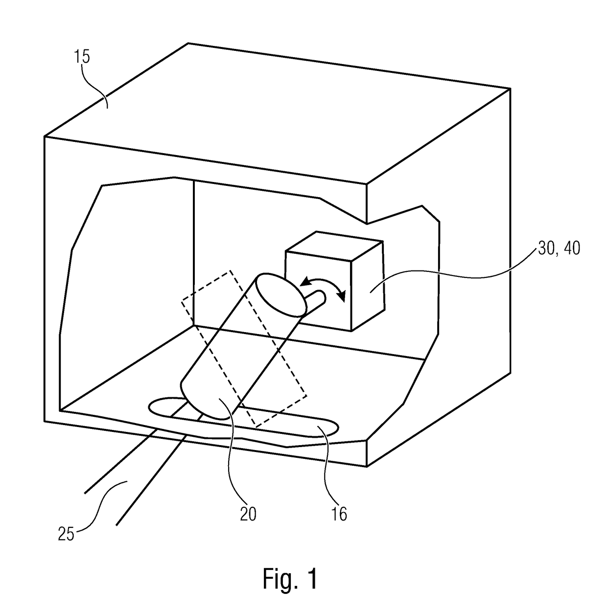
[0065]FIG. 1 schematically illustrates an inventive device which basically consists of a motor 30, an infrared temperature measuring head 20 arranged at the motor 30 or the motor axis, and a controller 40 arranged in the area of the motor 30. All the components mentioned are arranged so as to be protected in a casing 15, the casing 15 comprising an essentially longitudinal opening 16 in its lower area, i.e. in the direction towards the surface 110 of a newly applied road surface (not illustrated here). The fact that the infrared temperature measuring head 20 is arranged at the motor 30 or the motor axis causes the infrared temperature measuring head 20 to be twisted also with a twisting movement of the motor axis. This is indicated schematically in the figure by a broken-line position of the infrared temperature measurin...


PUM

PropertyMeasurementUnit
widthaaaaaaaaaa
widthaaaaaaaaaa
distanceaaaaaaaaaa

Abstract

A device for determining the temperature of a road building material applied by a construction machine in a placement width includes an infrared temperature measuring head, a motor and a controller. The infrared temperature measuring head is arranged to be twistable by the motor in a manner transverse to the direction of travel of the construction machine so as to scan the surface of the road building material to capture temperature measuring values of the surface of road building material during a rotational movement at a plurality of measuring points spaced apart from one another. The controller is configured to set a scanning speed as a function of a position of the measuring point.

Description

CROSS-REFERENCE TO RELATED APPLICATIONS[0001]This application claims priority from German Patent Application No. 102016207584.5, which was filed on May 3, 2016, and is incorporated herein in its entirety by reference.[0002]The present invention relates to the field of construction machines, in particular to a device for determining the temperature of a road building material, such as asphalt, bitumen, asphalt blend material or the like, newly applied by a construction machine, in particular a road finishing machine, in a mounting, or placement, width, the device being arranged at the construction machine in an area within the placement width and the device comprising an infrared temperature measuring head, a motor and a controller, the infrared temperature measuring head being arranged to be twistable, by the motor, in a manner transverse to the direction of travel of the construction machine, and being effective to capture temperature measuring values of the surface of the road bui...

Claims


Application Information

Patent Timeline
Patent Type & Authority Patents(United States)
IPC IPC(8): G01J5/08E01C23/01E01C19/48G01J5/04G01N33/42G01J5/02
CPCG01J5/089E01C19/48E01C23/01G01N33/42G01J5/041G01J5/047G01J5/026G01J5/07
Inventor BECHER, DOMINIKWATERMANN, MARCUSSHELSTAD, DAVID
Owner MOBA MOBILE AUTOMATION
Why Eureka
Try Eureka