Light-emitting touch-switch device and light-emitting touch-switch module

a technology of light-emitting touch and light-emitting diodes, which is applied in the direction of electronic switching, electrical apparatus, pulse technique, etc., can solve the problems of lowering the light-emitting efficiency of light-emitting diodes, and achieve the effect of large sensing area, efficient light emission and large sensing area

Active Publication Date: 2019-01-22
LITE ON OPTO TECH (CHANGZHOU) CO LTD +1
View PDF26 Cites 0 Cited by
  • Summary
  • Abstract
  • Description
  • Claims
  • Application Information

AI Technical Summary

Benefits of technology

[0006]Therefore, one object of the present invention is to provide a light-emitting touch-switch device that has a relatively large sensing area and that emits light efficiently.
[0007]Another object of the present invention is to provide a light-emitting touch-switch module that has a relatively large sensing area and that emits light efficiently.

Problems solved by technology

However, with the spring made from the non-light-transmissive metal, a majority of light emitted from the light emitting diode is blocked, thereby lowering the light-emitting efficiency of the light-emitting diode.

Method used


Image

  • Light-emitting touch-switch device and light-emitting touch-switch module
  • Light-emitting touch-switch device and light-emitting touch-switch module
  • Light-emitting touch-switch device and light-emitting touch-switch module

Examples


Embodiment Construction

[0029]Before the present invention is described in greater detail, it should be noted that like elements are denoted by the same reference numerals throughout the disclosure.

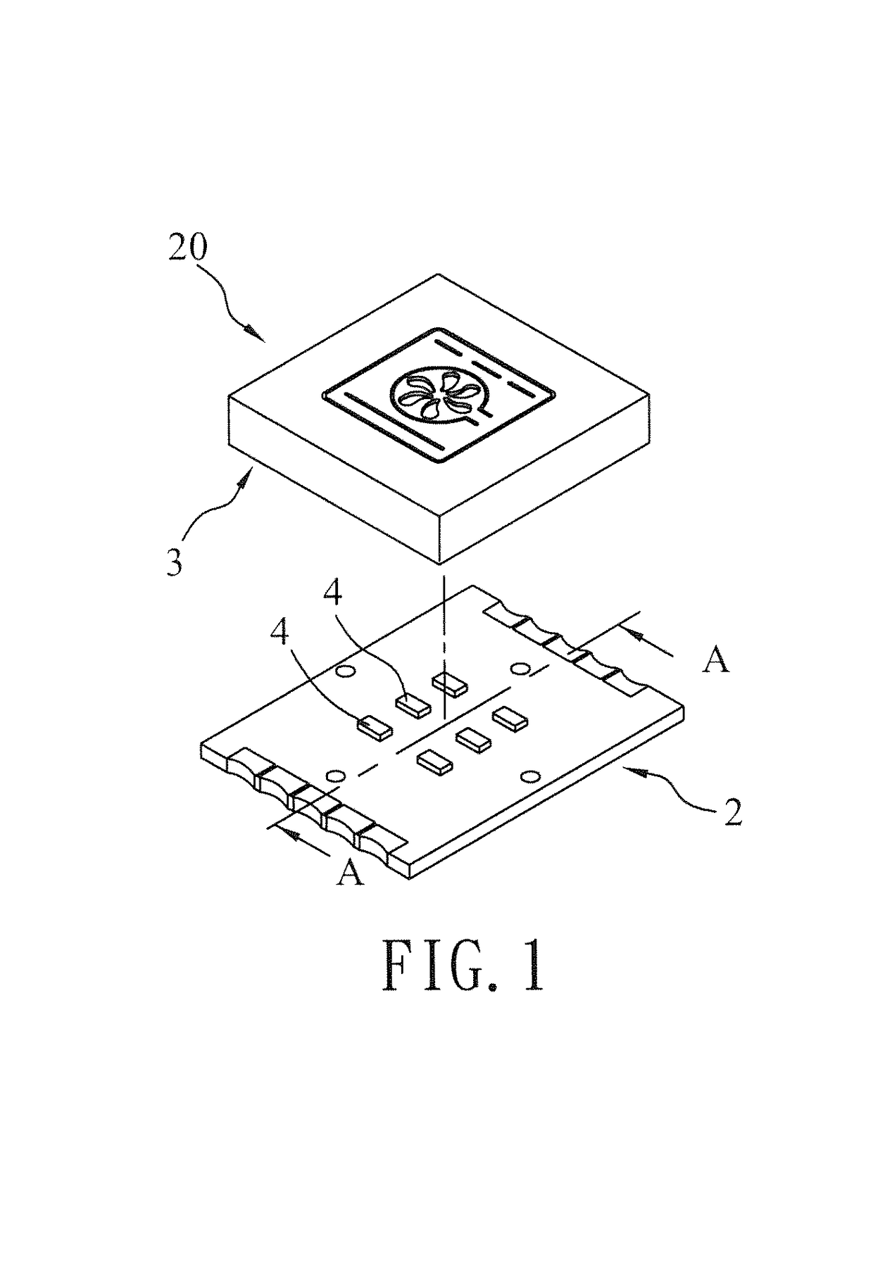
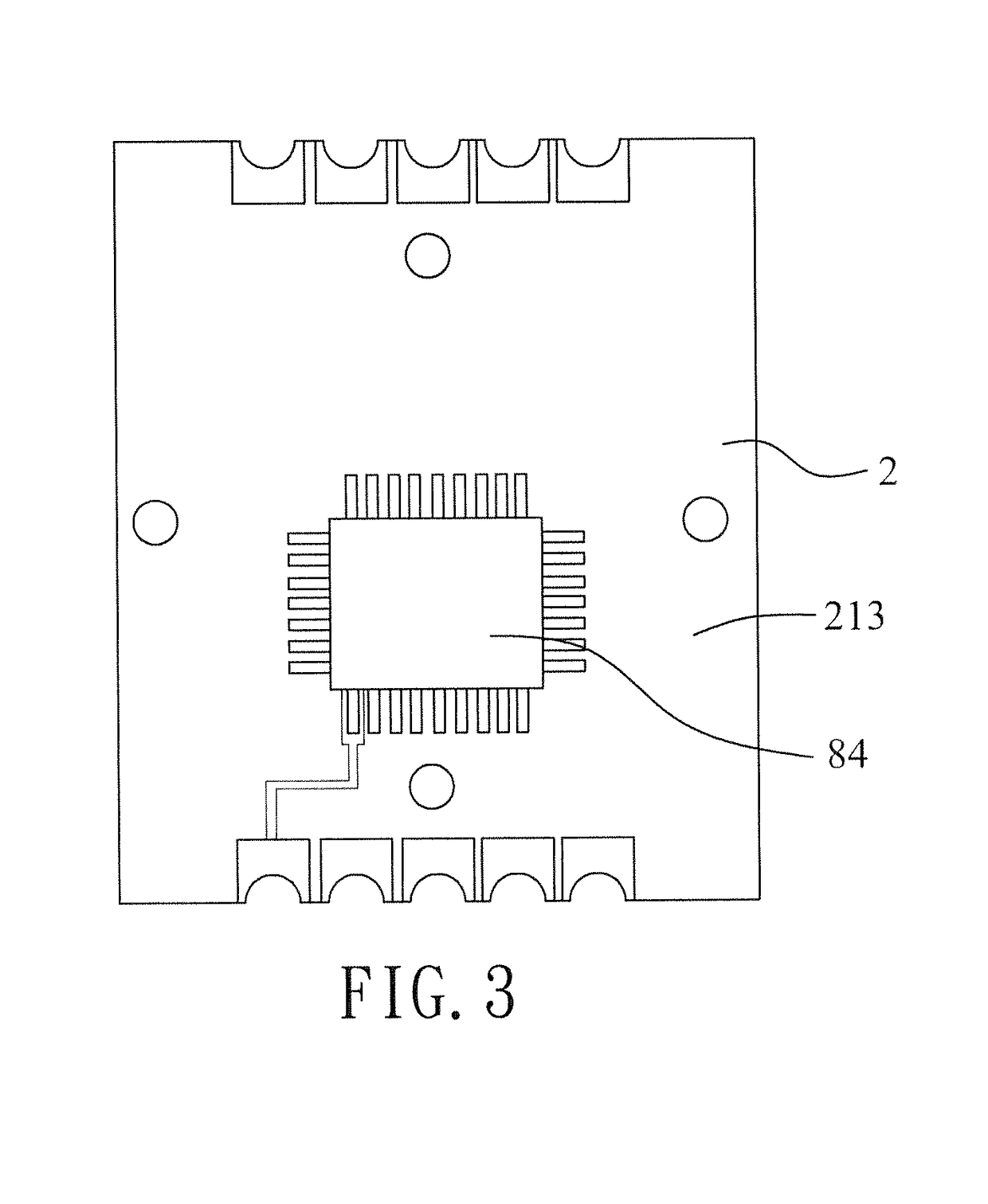
[0030]Referring to FIGS. 1 to 3, the first preferred embodiment of a light-emitting touch-switch device 20 is shown to be adapted for use with a sensing chip 84 (see FIG. 3). The sensing chip 84 generates a touch-sensing signal as a result of an electrically conductive object (e.g., a finger) being disposed in proximity of or in contact with the light-emitting touch-switch device 20. The touch-sensing signal may be used for actuating an external electronic appliance.

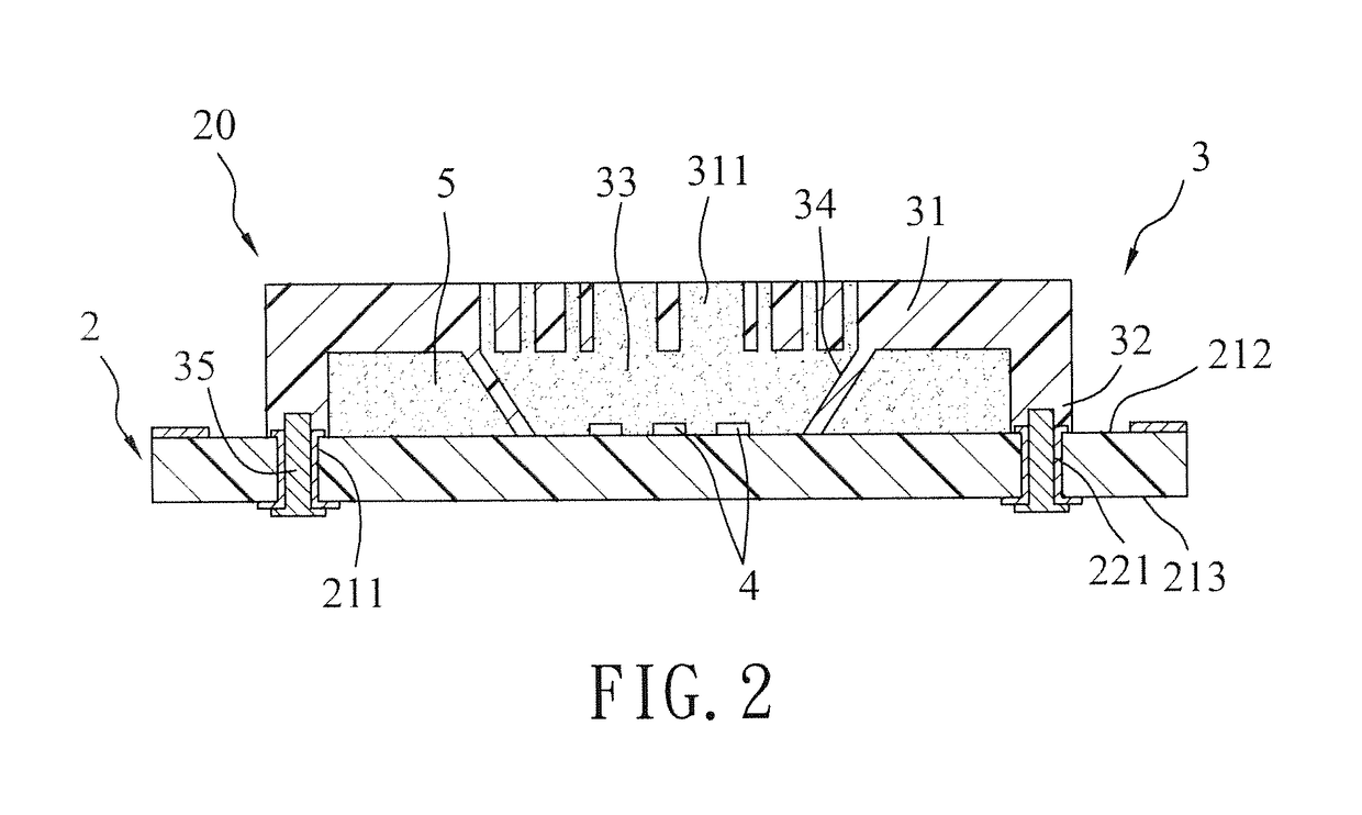
[0031]The first preferred embodiment of the light-emitting touch-switch device 20 includes a first circuit board 2, a cap unit 3 and a plurality of light emitting elements 4.

[0032]The first circuit board 2 has a top surface 212, a bottom surface 213, and is formed with at least one through hole 211 where a metal layer 221 is disposed therein. In grea...


PUM


Abstract

A light-emitting touch-switch device includes a first circuit board, a cap unit and a light-emitting element. The first circuit board is electrically coupled to a sensing chip. The cap unit is disposed on the first circuit board and that is at least partially made of an electrically conductive plastic material having a resistance of equal to or smaller than 1×10⁵Ω. The cap unit and the first circuit board cooperate to define a receiving space. The light-emitting element is disposed in the receiving space and is electrically coupled to the first circuit board. A light-emitting touch-switch module including the light-emitting touch-switch device is also disclosed.

Description

CROSS-REFERENCE TO RELATED APPLICATION[0001]This application claims priority of Chinese Patent Application No. 201310185960.5, filed on May, 17, 2013.BACKGROUND OF THE INVENTION[0002]1. Field of the Invention[0003]The invention relates to a touch-switch device and a touch-switch module, more particularly to a light-emitting touch-switch device and a light-emitting touch-switch module.[0004]2. Description of the Related Art[0005]U.S. Pat. No. 7,515,140 discloses a capacitive sensor including a metal spring that defines a central opening, in which a light emitting diode is disposed and serves as an indicator. However, with the spring made from the non-light-transmissive metal, a majority of light emitted from the light emitting diode is blocked, thereby lowering the light-emitting efficiency of the light-emitting diode. In addition, the capacitive sensor has a relatively small sensing area.SUMMARY OF THE INVENTION[0006]Therefore, one object of the present invention is to provide a lig...

Claims


Application Information

Patent Timeline
Patent Type & Authority Patents(United States)
IPC IPC(8): H03K17/96
CPCH03K17/962H03K2217/960785H03K2217/960755
Inventor CHEN, SHUO-HUNGLIN, CHIN-KUAN
Owner LITE ON OPTO TECH (CHANGZHOU) CO LTD
Why Eureka
Try Eureka