Cannulated bone screw and methods of use therefof

a cannulated bone screw and screw technology, applied in the field of bone screws, can solve the problems of difficult process, complex handling of the plug member, and treatment of the bone,

a cannulated bone screw and screw technology, applied in the field of bone screws, can solve the problems of difficult process, complex handling of the plug member, and treatment of the bone,

US10188442B2Active Publication Date: 2019-01-29CLARIANCE MEDICAL DISTRIBUTION

Image

  • Cannulated bone screw and methods of use therefof
  • Cannulated bone screw and methods of use therefof
  • Cannulated bone screw and methods of use therefof

Examples


Embodiment Construction

[0065]The following detailed description will be better understood when read in conjunction with the drawings. For the purpose of illustrating, the device is shown in the preferred embodiments. It should be understood, however that the application is not limited to the precise arrangements, structures, features, embodiments, and aspect shown. The drawings are not drawn to scale and are not intended to limit the scope of the claims to the embodiments depicted. Accordingly it should be understood that where features mentioned in the appended claims are followed by reference signs, such signs are included solely for the purpose of enhancing the intelligibility of the claims and are in no way limiting on the scope of the claims.

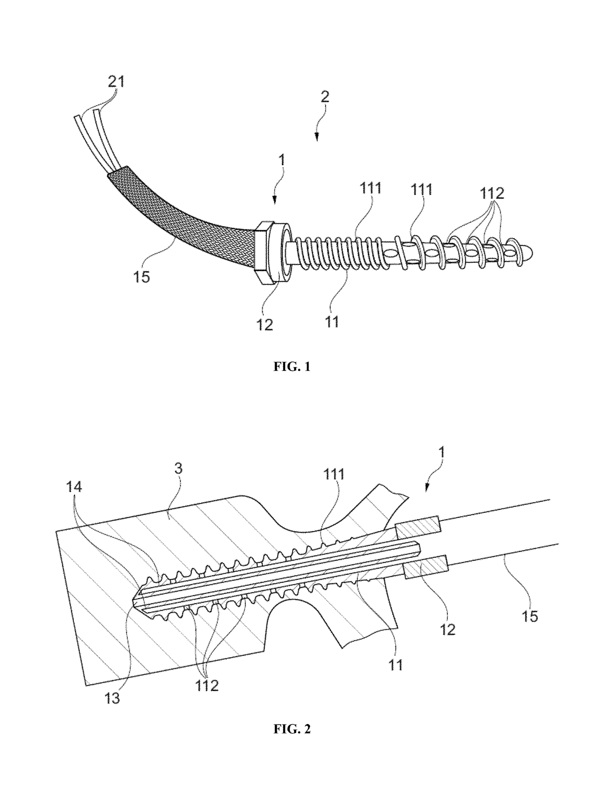
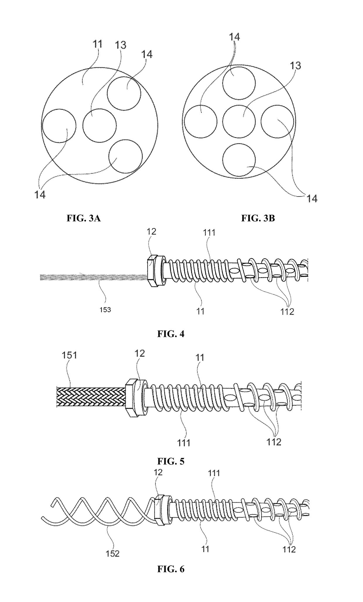
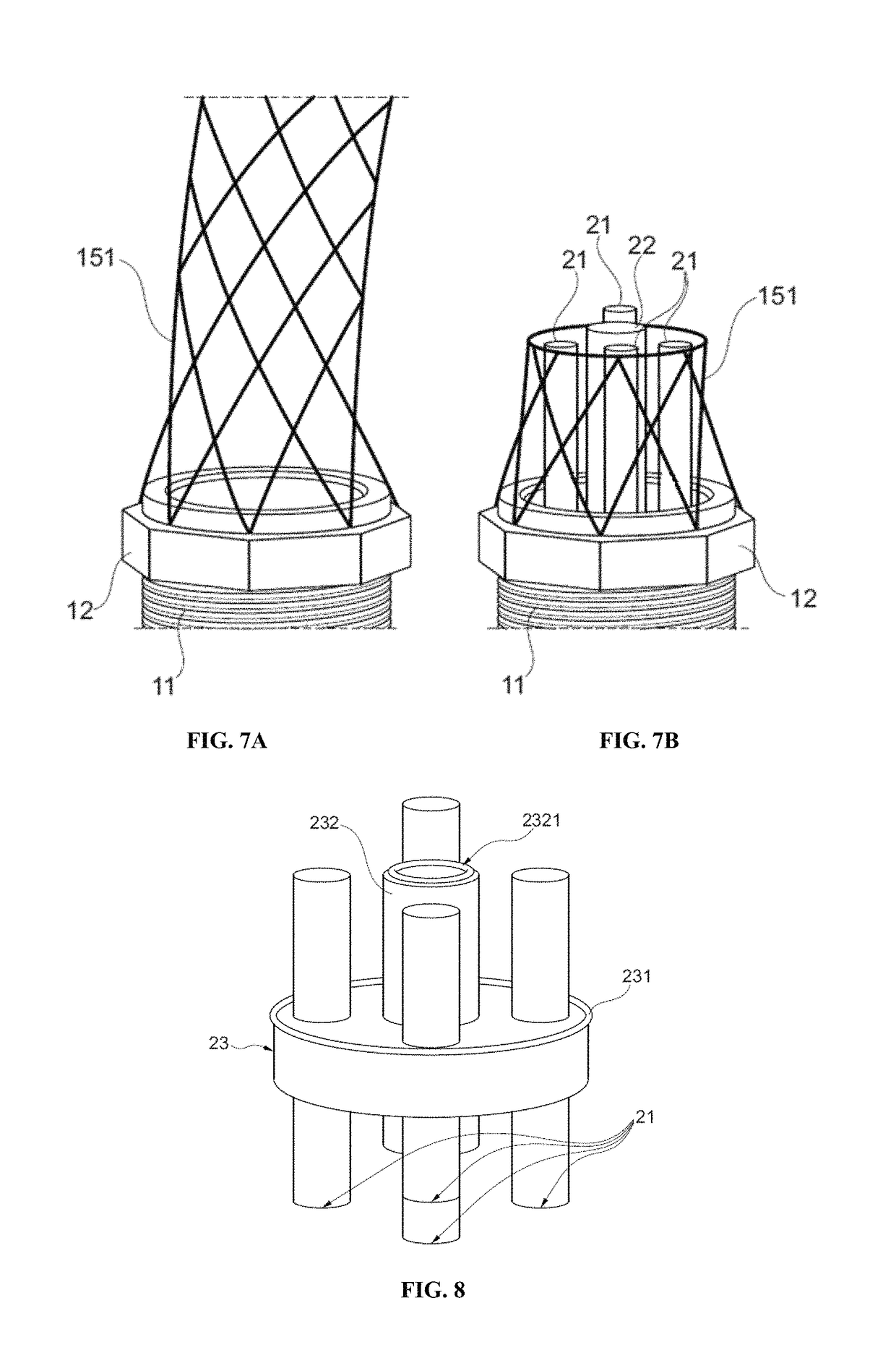
[0066]FIGS. 1 to 9 show a bone screw or a system comprising the bone screw according to the invention. As depicted in FIG. 2, the bone screw 1 comprises a screw body 11 for anchoring in the bone, e.g. a vertebra 3. Said screw body 11 comprises a proximal end, a d...


PUM


Abstract

The present invention relates to a bone screw comprising a screw body comprising a proximal end, a distal end, a longitudinal axis and a thread along all or a portion of said screw body; a screw head; a through bore extending coaxially through said screw head and through said screw body from the proximal end up to the distal end; at least three blind channels angularly-disposed around the bore; each of said channels being configured to receive a perforated catheter or a needle; a plurality of radially-disposed fenestrations; wherein each of said channels is connected to an exterior of said screw body through at least one fenestration; and flexible directing means secured to the screw head. The present invention also relates to a system comprising such bone screw, to a method of delivering a substance to an intervertebral disc using the system according to the invention and to a method of treating vertebral tumor using the system according to the invention.

Description

FIELD OF INVENTION[0001]The present invention pertains to the field of bone screws. In particular, the invention relates to cannulated bone screws and methods of use thereof for the treatment of bone.BACKGROUND OF INVENTION[0002]Delivery of drugs or therapeutics to bones is an often desirable but difficult to achieve process, especially if one desire to focus the delivery to the interior of a bone or to a particular area in a bone.[0003]US 2014 / 0236242 teaches to use a screw for bone fixation comprising an elongate shank defining an internal longitudinal passage and at least one shank aperture in communication with the internal longitudinal passage. However with such device, the discharge of substances within the bone is mainly distal due to the distal opening required to insert a guiding wire. Such guiding wire is necessary for minimally invasive surgery. Minimally invasive surgery, which is applied to an increasing number of cases, required indeed guiding wires to position an impl...

Claims


Application Information

Patent Timeline
29 Jan 2019
Publication
US10188442B2
IPC
A61B17/86; A61M25/00; A61M5/142; A61B17/56; A61B17/90
CPC
A61B17/864; A61B17/8605; A61M25/007; A61M5/14276; A61B2017/90; A61B2017/561; A61B17/90
Inventors
MAZEL, CHRISTIAN