Steam accumulator comprising a latent heat accumulator and a steam thermocompressor

Active Publication Date: 2019-01-29
CURRENTA
View PDF26 Cites 0 Cited by
  • Summary
  • Abstract
  • Description
  • Claims
  • Application Information

AI Technical Summary

Benefits of technology

[0026]It has been surprisingly found that the above-described problem can be solved by connecting one or more steam thermocompressors and

Problems solved by technology

The duration of decoupled operation is limited by the capacity of the steam storage.
In spite of the advantages of storing the heat of condensation of the steam in a latent heat store (phase-change storage medium), there remains a grave problem which greatly limits the potential for increasing the flexibilit

Method used


Image

  • Steam accumulator comprising a latent heat accumulator and a steam thermocompressor
  • Steam accumulator comprising a latent heat accumulator and a steam thermocompressor

Examples


Example

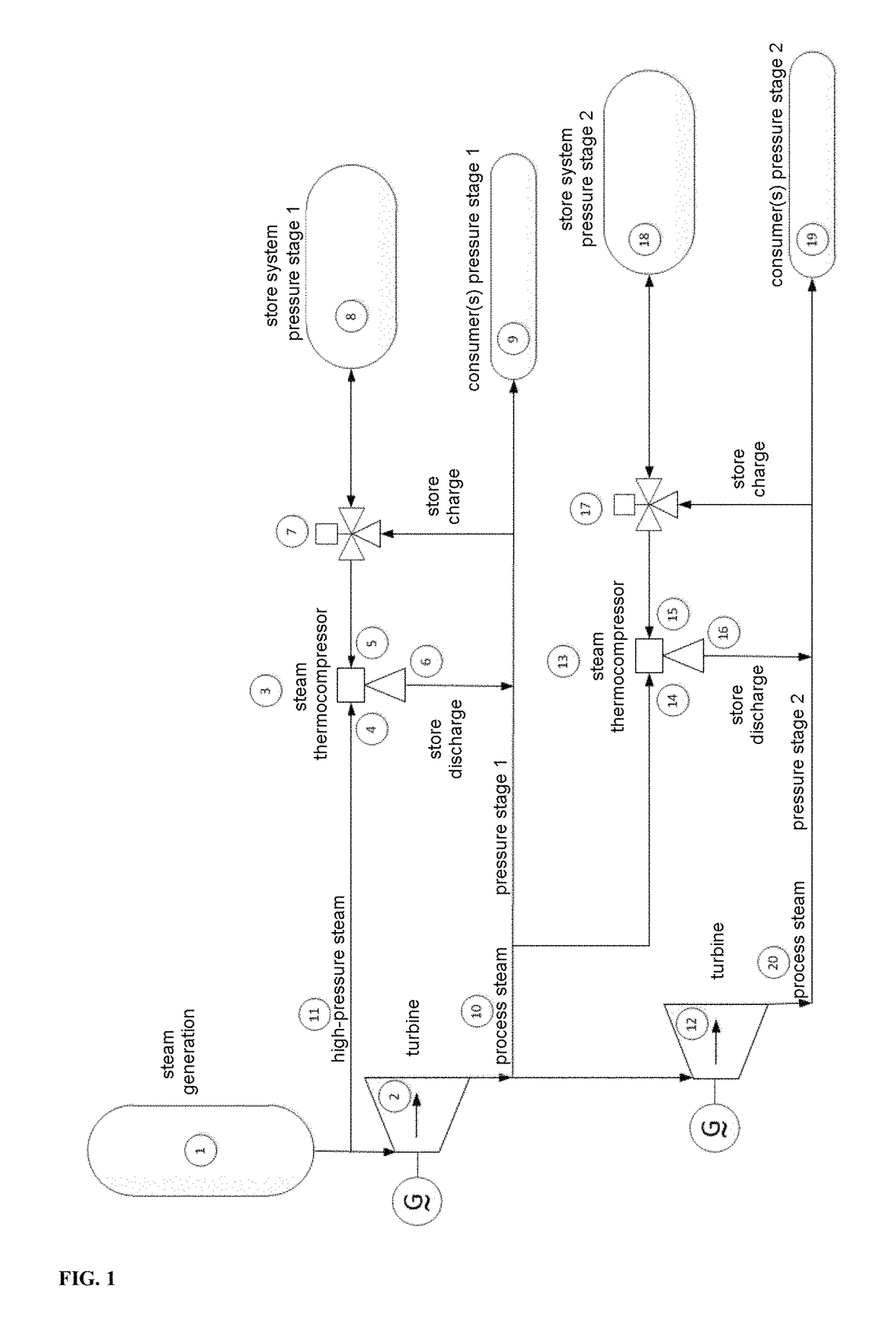
[0042]The steam thermocompressor can for example be used, according to a first preferred embodiment, during discharge of the storage system.

[0043]In this configuration, which is illustrated in FIG. 1, the pressure of the discharge steam is raised by thermocompression to the pressure level of the process steam used for charging. In the illustration, valves are included only for clarification. For charging the storage system, process steam 10 of pressure stage 1 is fed via the valve 7 to the storage system 8 of pressure stage 1. When the storage system 8 is discharged, the steam thermocompressor 3 is connected to high-pressure steam 11 on the driving side 4 and is connected via the valve 7 to the storage system 8 on the suction side 5. The high-pressure steam 11 is taken from the steam generation 1 or from a line directly connected thereto. The compressed discharge steam is fed, via the outlet 6 of the thermocompressor 3, back into the steam supply system as process steam 10 at the pr...


PUM


Abstract

The present invention relates to a method for decoupling the provision of electricity and high-pressure steam of a combined heat and power plant which has the primary purpose of providing process steam, i.e. which is heat-led.

Description

CROSS-REFERENCE TO RELATED APPLICATIONS[0001]This application is a 371 of PCT / EP2014 / 077031, filed Dec. 9, 2014, which claims foreign priority benefit under 35 U.S.C. § 119 of German Application 10 2013 225 543.8 filed Dec. 11, 2013, the disclosures of which are incorporated herein by reference.BACKGROUND OF THE INVENTIONField of the Invention[0002]The instant invention relates to the field of power generation, specifically, conservation of heat energy produced by steam generated during power generation, and more specifically, to storage and use of heat energy produced by steam.[0003]Description of Related Art[0004]The present invention relates to a method for decoupling the provision of electricity and high-pressure steam of a combined heat and power plant which has the primary purpose of providing process steam, i.e. which is heat-led operated.[0005]The increasing generation of electricity from fluctuating renewable energy (FRE) sources requires increased flexibility for thermal p...

Claims


Application Information

Patent Timeline
IPC IPC(8): F01K1/08F01K3/00F01K17/04F01K17/00
CPCF01K1/08F01K3/006F01K17/04F01K17/00Y02P80/15Y02E20/14
Inventor FRANCK, RUDIGER
Owner CURRENTA
Why Eureka
Try Eureka