Low temperature electrical heating heat exchange device

A heat exchange device and electric heating technology, which is applied in the direction of heat storage heaters, fluid heaters, heat exchangers, etc., can solve the problems of large volatilization and waste of heat exchange media, uneven heating of heat exchange media, and large dimensions , to achieve the effect of reducing the overall size and improving the utilization rate of the usable area

Pending Publication Date: 2020-10-13
CHENGDU CRAER CRYOGENIC EQUIP
View PDF0 Cites 0 Cited by
  • Summary
  • Abstract
  • Description
  • Claims
  • Application Information

AI Technical Summary

Problems solved by technology

[0005] (1) The overall size of the equipment is large, and the thermal expansion and contraction deformation and stress caused by temperature differences after the low-temperature medium enters the equipment are more obvious;
[0006] (2) During the operation of the existing equipment, the volatilization and waste of the heat exchange medium is relatively large, especially in special environments, the heat exchange medium solution will decrease with time;
[0007] (3) The heating of the heat exchange medium inside the existing equipment is not uniform, resulting in poor heating effect on the low temperature medium

Method used


Image

  • Low temperature electrical heating heat exchange device
  • Low temperature electrical heating heat exchange device
  • Low temperature electrical heating heat exchange device

Examples


Embodiment 1

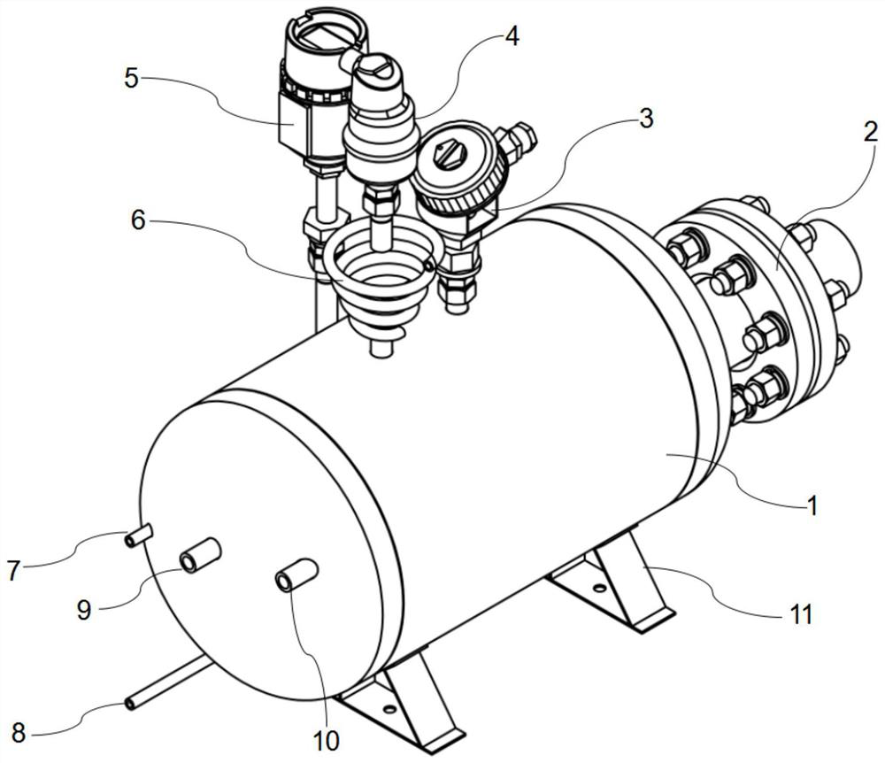
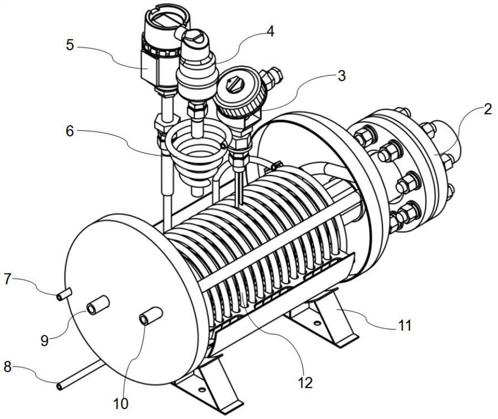
[0035] In this embodiment, a low-temperature electric heating heat exchange device is specifically disclosed, which is mainly composed of an electric heating rod 2, a heat exchanger shell 1, a coil group 12, a liquid level gauge 3, an automatic discharge valve, and a temperature transmitter 5 and other components, in order to be able to realize the gasification or heating function of the low-temperature medium, the specific design is as follows:

[0036] like figure 1 , figure 2 As shown, the heat exchanger shell 1 is used as the carrier of the device and the heat exchanger shell 1 is set in a cylindrical shape. Preferably, the heat exchanger shell includes a cylindrical body and elliptical heads that are hermetically fitted at both ends of the cylindrical body, and the coil group is placed on the central axis of the cylindrical body or below the central axis. The top of the body is equipped with an automatic exhaust valve, a liquid level gauge and a temperature transmitter...

Embodiment 2

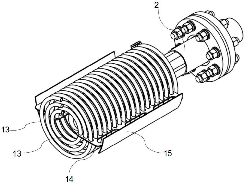
[0047] On the basis of Embodiment 1, in order to realize that the coil group 12 is firmly installed inside the heat exchanger housing 1, to ensure the normal operation of the coil group 12, as image 3 , Figure 4 as well as Figure 5 As shown, it also includes a fixing plate 14 arranged in the heat exchanger shell 1, and a plurality of fixing holes 17 are opened on the fixing plate 14, and each fixing hole 17 is arranged along the column direction and the row direction, and is located in the same column Each fixing hole 17 in the direction corresponds to each layer of coiled tubes 13 respectively, and each fixing hole 17 in the same row direction matches the spiral shape of the same layer of coiled tubes 13 respectively. In this embodiment, three layers of coils 13 are arranged and the distances between adjacent two layers of coils 13 are equal. On the fixing plate 14, a There are three rows of fixing holes 17 (the row is the axial direction of the heat exchanger shell 1), ...


PUM


Abstract

The invention discloses a low temperature electrical heating heat exchange device and belongs to the technical field of low temperature medium heating. The low temperature electrical heating heat exchange device comprises a heat exchanger shell, and a heat exchange medium circulates in the heat exchanger shell. The low temperature electrical heating heat exchange device further comprises a coil pipe set arranged in the heat exchanger shell, a low temperature medium circulates through the coil pipe set, a hollow cavity is reserved in the coil pipe set, and a cryogenic medium inlet and a cryogenic medium outlet are formed outside the heat exchanger shell and communicate with the two end ports of the coil pipe set respectively. The low temperature electrical heating heat exchange device further comprises an electrical heating rod arranged on the heat exchanger shell, and the electrical heating rod stretches into and penetrates through the hollow cavity to achieve the purposes that the stable running of equipment can be ensured while the low temperature medium can be heated or gasified.

Description

technical field [0001] The invention belongs to the technical field of low-temperature medium heating, and in particular relates to a low-temperature electric heating heat exchange device. Background technique [0002] Cryogenic fluids generally refer to fluids whose boiling point is lower than 120 Kelvin (abbreviated as K), that is, about minus 153 degrees Celsius. Cryogenic fluid heating is different from conventional fluid heating: on the one hand, the heating amount must be strictly controlled, and the heat provided by the heater and the heat absorbed by the low-temperature fluid must be accurately calculated; on the other hand, the heating must be uniform, otherwise it is easy to appear low-temperature fluid Vaporization, danger of overpressurization. [0003] The existing low-temperature fluid heating equipment is mainly used for the gas supply of hydrogen-oxygen fuel cells such as vehicles, ships, and submersibles, the gas supply of vehicle-mounted LNG gas engines, a...

Claims


Application Information

Patent Timeline
Patent Type & Authority Applications(China)
IPC IPC(8): F24H7/02F24H9/00F24H9/18F24H9/20F28D7/02
CPCF24H7/0233F24H9/0005F24H9/1818F24H9/2021F28D7/024
Inventor 吴长宇明长友邹波匡龙洋杨志林
Owner CHENGDU CRAER CRYOGENIC EQUIP
Why Eureka
Try Eureka