Door operator having lock mechanism

a technology of operator and lock mechanism, which is applied in the direction of door/window protective devices, mechanical devices, wing accessories, etc., can solve the problems of not being suitable for a big rolling door, the torsional strength of the engaging rotary block is relatively weak, and the chain disk tends to slip at the initial pull, so as to reduce the rotational speed of the drive shaft, reduce the rotational speed of the electric motor, and ensure the effect of safety

Active Publication Date: 2019-02-12
HSIEH CHUNG HSIEN
View PDF18 Cites 3 Cited by
  • Summary
  • Abstract
  • Description
  • Claims
  • Application Information

AI Technical Summary

Benefits of technology

[0014]A further object of the present invention is to provide a bidirectional rotary block for the locking mechanism, which has a diameter that is less than that of conventional one. It is simple in structure and does not require a special machine for machining. As such, it is easy to machine and cheap in manufacturing cost.
[0026]Preferably, the present invention further comprises a reduction mechanism connected in between the other end of the motor drive shaft of the electric motor and an output shaft. The reduction mechanism reduces the rotational speed of the electric motor by means of the cooperation between a sun gear set, a planetary gear set, and an internal gear set, and transmits the reduced speed to the output shaft. The reduction mechanism is designed to control the speed of the rolling door rolling up or down. The reduction speed and the gear ratio can be selected as desired depending on the installed location of the rolling door and the weight of the door panel.

Problems solved by technology

However, the above engaging rotary block has the following disadvantages in manufacture and use:(1) Since the engaging rotary block includes axial slots having planar, included angles, the chain disk tends to slip at the initial pull.
That is to say, the engaging rotary block has a relatively weak torsional strength, and thus is not suitable to be used on a big rolling door.(2) The axial slot is trapezoidal in shape, and thus has a large diameter, and needs a special machine for machining.
As such, the manufacturing is time-consuming and expensive.(3) The axial slot is complicated, and thus requires high precision in machining, and the defective rate of the product is high.

Method used


Image

  • Door operator having lock mechanism
  • Door operator having lock mechanism
  • Door operator having lock mechanism

Examples


Embodiment Construction

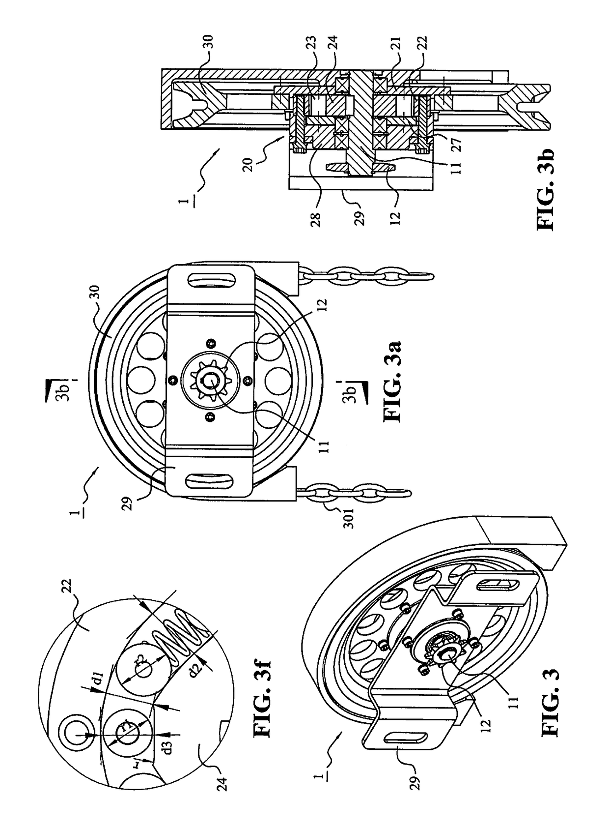
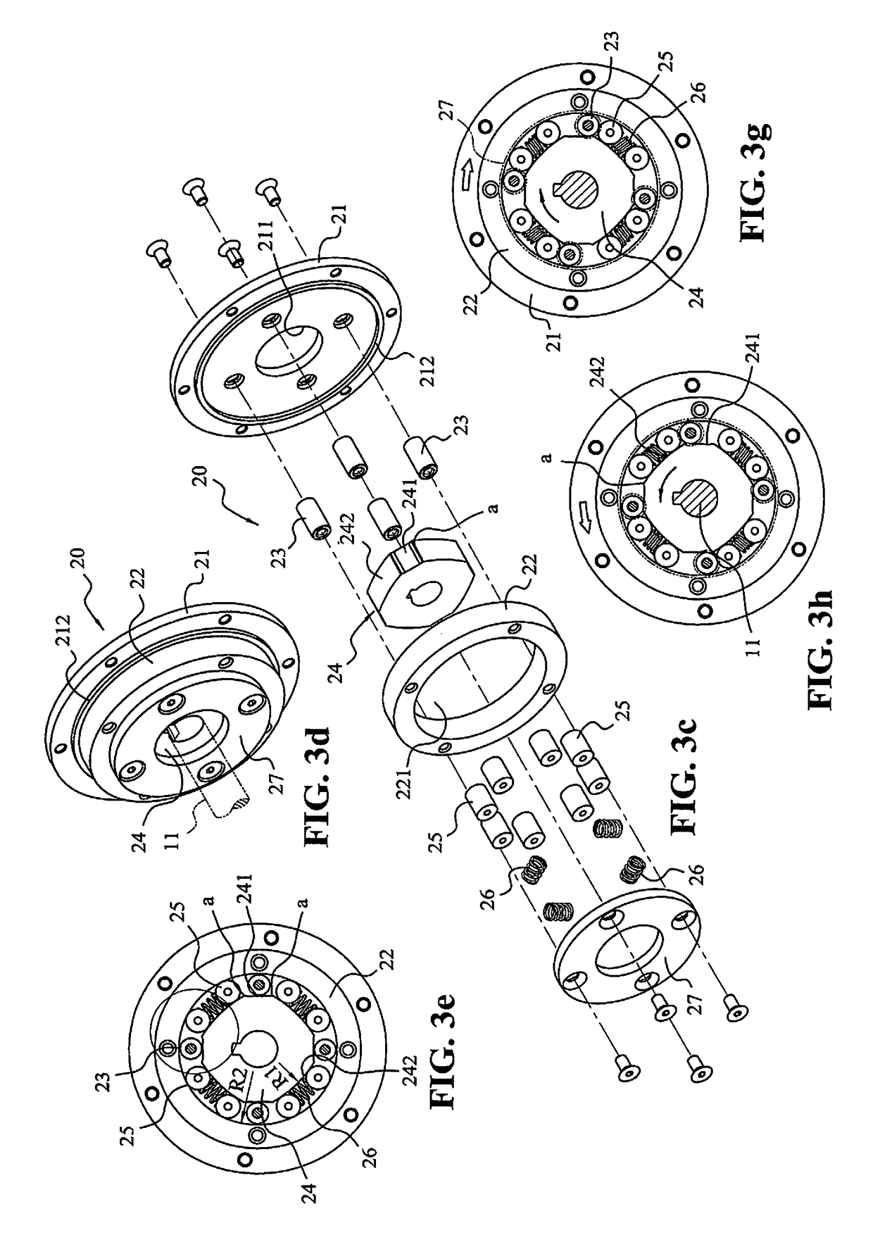
[0052]Referring to FIGS. 3 and 3a-3h which show a lock mechanism of a door operator of preferred embodiment of the present invention, which includes a bidirectional rotary block. As shown in the drawings, a manual type door operator 1 includes a rotary shaft 11 having one end serves as a force applying end and the other end as the output end, and a locking mechanism 20 disposed between the force applying end and output end of the rotary shaft 11 for braking the rotary shaft 11. The force applying end of the rotary shaft 11 is fixedly connected to a chain disk 30, and the chain disc 30 is circumferentially surrounded by a chain 301. Pulling the chain 301 will actuate to rotate the rotary shaft 11. The output end of the rotary shaft is fixedly connected to an output wheel 12. The output wheel 12 drives the reel shaft to roll up or unwind the rolling door (not shown) by means of the cooperation between a known chain and the reel shaft.

[0053]As shown in FIG. 3c, the locking mechanism 20...


PUM


Abstract

A door operator comprises a rotary shaft, a chain disk for rotating the rotary shaft, and a locking mechanism for locking the rotary shaft. The locking mechanism comprises a bidirectional rotary block, a plurality of push pins and anti-rotation posts. When the chain disk rotates, the push pins urge the bidirectional rotary block to rotate the rotary shaft, and when the rotary shaft rotates, the of anti-rotation posts lock the bidirectional rotary block, and preclude the rotary shaft from rotating.

Description

BACKGROUND OF THE INVENTION[0001]1. Field of the Invention[0002]The present invention relates to a door operator, in particular to a door operator comprising a locking mechanism with a bidirectional rotary block.[0003]2. Description of the Prior Art[0004]FIG. 1 shows a locking mechanism having a chain disk for a manual door operator disclosed in U.S. Pat. No. 8,915,287 issued to the Applicant. The locking mechanism comprises a wedge wheel (36′) fixedly connected to a drive shaft (37′) and accommodated in a ring socket (34′). The wedge wheel (36′) includes a plurality of axial slots (361′) each having two bottom surfaces (362′) and two side walls (364′). Each of the bottom surfaces (362′) has a first end portion (P1′) and a second end portion (P2′). The first end portion (P1′) is spaced from the inner wall of the ring socket (34′) by a first distance (D1′). The second end portion (P2′) is spaced from the inner wall of the ring socket (34′) by a second distance (D2′). The first distan...

Claims


Application Information

Patent Timeline
Patent Type & Authority Patents(United States)
IPC IPC(8): E06B9/74E06B9/80E05F11/04E06B9/76E06B9/84F16D51/32F16D65/22E05F5/04
CPCE06B9/80E05F11/04E06B9/74E06B9/76F16D51/32F16D65/22E06B9/84E06B2009/807E05F2005/043E06B2009/801E06B9/78
Inventor HSIEH, CHUNG-HSIEN
Owner HSIEH CHUNG HSIEN
Why Eureka
Try Eureka