Supercharge Your Innovation With Domain-Expert AI Agents!

Shooting device and unmanned aerial vehicle

a shooting device and unmanned aerial technology, applied in the field of unmanned aerial vehicles, can solve the problems of low response speed, inconvenient control of shooting effect, and high requirements for lenses, so as to improve the response speed of the shooting device, improve the quality of shot images, and increase the shooting visual angle

Inactive Publication Date: 2019-02-19
EWATT TECH CO LTD
View PDF3 Cites 0 Cited by
  • Summary
  • Abstract
  • Description
  • Claims
  • Application Information

AI Technical Summary

Benefits of technology

The present invention is a shooting device and unmanned aerial vehicle that allows for convenient control, large shooting visual field, high response speed, and high image quality. The device includes a driving part that rotates the first and second reflectors to vibrate at a preset frequency, which ensures quality image during flying. The first and second reflectors can also rotate relatively to change the light path, improving the response speed of the device without rotating the entire shooting device. The invention solves the technical problem of inconvenient control, low response speed, high requirements on lens, and high cost of the shooting device for the unmanned aerial vehicle in the prior art.

Problems solved by technology

In the former mode, the shooting device is heavy, the accurate control of the shooting effect is inconvenient to achieve due to the overall rotation, the response speed is low, and the requirements on the lens are high.
In the latter mode, since the multiple shooting lenses are adopted, the shooting images are incomplete, the requirements on the lenses are high, and the cost is relatively higher.

Method used


Image

  • Shooting device and unmanned aerial vehicle

Examples


Embodiment Construction

[0020]To better understand the aforementioned technical solutions, the aforementioned technical solutions will be illustrated below in detail in conjunction with the accompany drawings in the description and specific embodiments.

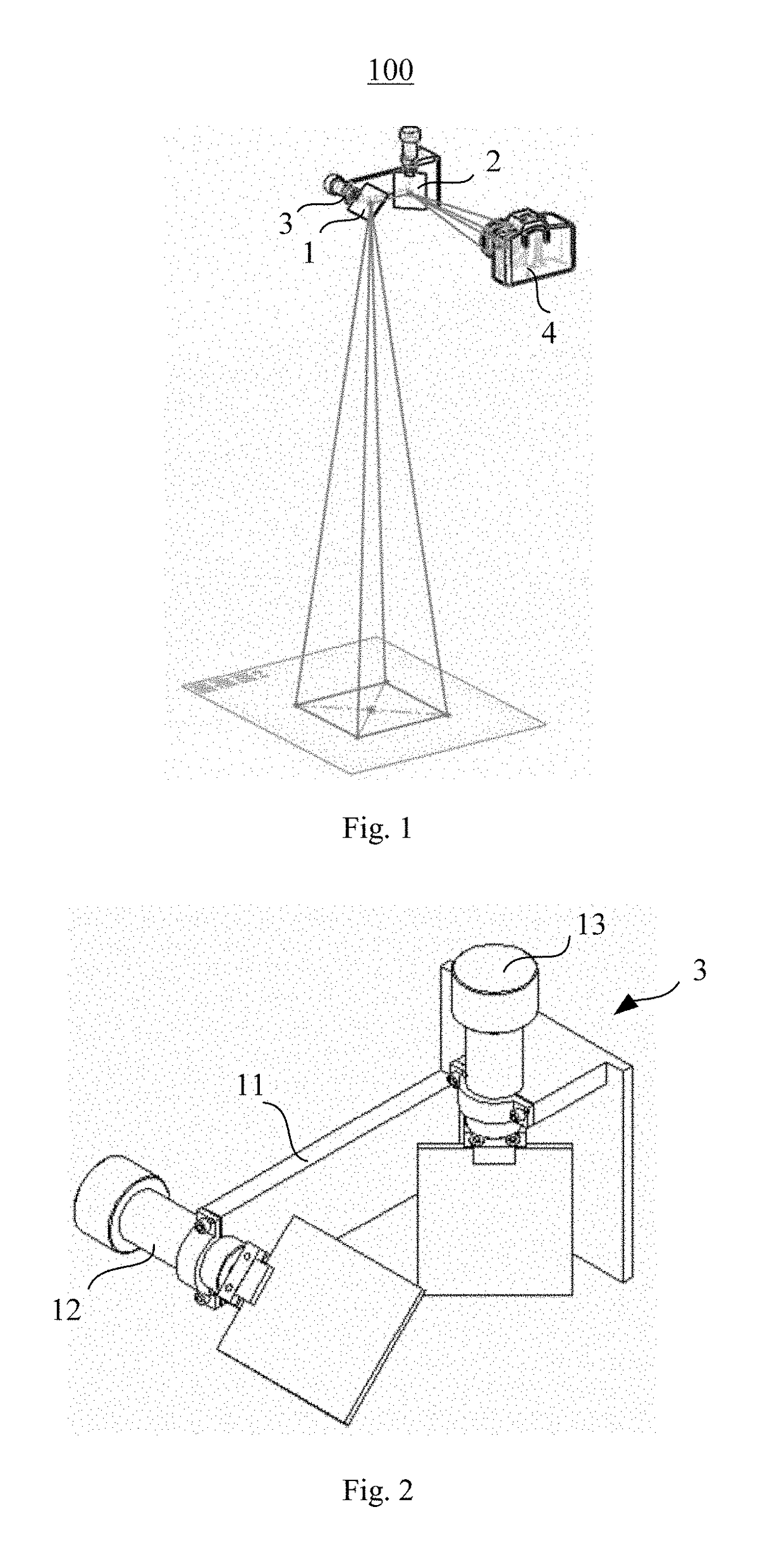
[0021]FIG. 1 is a structural schematic diagram of a shooting device in a preferred embodiment of the present application. As shown in FIG. 1, the shooting device 100 includes a first reflector 1, a second reflector 2, a bracket 3, driving parts and a camera 4.

[0022]The first reflector 1 and the second reflector 2 change the light path of light, and the second reflector 2 is arranged to be opposite to a reflecting surface of the first reflector 1. Please refer to FIG. 2, the bracket 3 is used for supporting the first reflector 1 and the second reflector 2, the bracket 3 includes a connecting plate 11, a first rotating seat 12 and a second rotating seat 13, the first rotating seat 12 is fixedly connected with one end of the connecting plate 11 in a rotatable m...


PUM


Abstract

The present invention discloses a shooting device and an unmanned aerial vehicle. The shooting device includes: a first reflector; a second reflector arranged to be opposite to a reflecting surface of the first reflector; a bracket, wherein the bracket includes: a connecting plate, a first rotating seat, which is fixedly connected with one end of the connecting plate in a rotatable manner and is used for clamping the first reflector, and a second rotating seat, which is fixedly connected with the other end of the connecting plate in the rotatable manner and is used for clamping the second reflector; driving parts, including a first driving part and a second driving part used for respectively driving the first rotating seat and the second rotating seat to rotate; and a camera arranged to be opposite to the reflecting surface of the second reflector. The technical problems of inconvenient control, low response speed, high requirements on lens and high cost of the shooting device for the unmanned aerial vehicle in the prior art are solved.

Description

RELATED APPLICATIONS[0001]This application is a Non-provisional Application under 35 USC 111(a), which claims Chinese Patent Application Serial No. 201510856080.5, filed Nov. 30, 2015, the disclosure of all of which are hereby incorporated by reference in their entirety.FIELD OF THE INVENTION[0002]The present invention relates to the technical field of unmanned aerial vehicles, and particularly to a shooting device and an unmanned aerial vehicle.BACKGROUND OF THE INVENTION[0003]A pilotless aircraft is referred to as an “unmanned aerial vehicle”, and is an unmanned aircraft that is manipulated by radio remote control equipment and its own program control device. No cockpit is mounted on the unmanned aerial vehicle, but an autopilot, the program control device, a signal collection device and other equipment are installed thereon. Personnel on the ground, on a naval vessel or a master remote control station carries out tracking, positioning, remote control, telemetering and digital tra...

Claims


Application Information

Patent Timeline
Patent Type & Authority Patents(United States)
IPC IPC(8): H04N7/18B64D47/08B64C39/02G02B26/10G03B15/00
CPCB64D47/08B64C39/024G02B26/105H04N7/183G03B15/006G03B2205/0023B64C2201/127B64U2101/30B64U20/87
Inventor ZHAO, GUOCHENGWAN, YONGZHANG, KAI
Owner EWATT TECH CO LTD
Features
  • R&D
  • Intellectual Property
  • Life Sciences
  • Materials
  • Tech Scout
  • Unparalleled Data Quality
  • Higher Quality Content
  • 60% Fewer Hallucinations
Learn More