Methods for thread transection of a soft tissue

a soft tissue and transection technology, applied in the field of soft tissue transection methods, can solve the problems of difficult to manipulate the introducer needle or router to exit the patient, not always possible, impossible to exit, etc., and achieve the effect of minimizing the disruption of the surrounding tissue, easy and fas

Active Publication Date: 2019-02-26
GUO JOSEPH +2
View PDF2 Cites 2 Cited by
  • Summary
  • Abstract
  • Description
  • Claims
  • Application Information

AI Technical Summary

Benefits of technology

[0010]The present invention provides for the minimally-invasive transection of tissue such as a ligament. The method and apparatus obviate the need for any incisions, minimizes disruption of the tissue surrounding the target ligament, enables a smooth kerf-less cut of the target ligament to be achieved, requires no suturing and can be easily and quickly performed in a clinic setting.
[0013]Particular routing tools of the present invention enables the cutting element to be easily and quickly introduced and routed into position about the target ligament (or other structure to be dissected) with minimal disruption or trauma to the surrounding tissue. The routing tools may take the form of a pair of introducer needles which are utilized together in creating the passageway needed to rout the cutting element about the target ligament. A first hollow introducer needle is initially advanced into a first location on the patent adjacent to the target ligament. The first introducer needle is advanced past one side of the ligament until the distal end of the needle exits the patient at a second location. However, due to the presence of a hard tissue, the physician may not be able to advance the needle any further without either damaging tissue or pushing the distal tip of the needle to a location which is not the desired exit location. When this occurs, a second hollow introducer needle is inserted into the second location and advanced towards the distal tip of the first needle. The needles are dimensioned so that one of the lumens of the introducer needles receives the other introducer needle thereby creating a passage which runs one across one side of the target ligament and has an entry location and exit location on the patient. In this manner, the first introducer needle is used to create a first access port at a first location proximal to the target ligament and laterally adjacent thereto. The second introducer needle is then used to create a second access port at a second location just distal to the target ligament. The distal end of the introducer needle having the smaller diameter is then inserted into the larger lumen of the other introducer needle in vivo to create a passage across one side of the target ligament. The passage is then used to pass the cutting element therethrough to allow one end of the cutting element to extend from each of the access ports. The use of two introducer needles allows the physician to access the target ligament from two sides of the ligament, rather than one needle, which may make the creation of the passage across the target ligament easier to attain. The cutting element is extended through one end of the needle to the other end allowing approximately one half of the cutting element to be pulled from one end of the needle. The needle is then retracted from the patient to leave the cutting element in place such that a sizable portion thereof protrudes from both of the access port locations.
[0014]In another aspect of the present invention, the first introducer needle has a lumen sized to fit over the outer diameter of the shaft of the second introducer needle. Again, the first introducer needle is advanced through the first location as far as is safely possible. The smaller diameter shaft of the second introducer needle is then inserted into the patient at the desired second location and is advanced near the distal end of the first introducer needle. Imaging devices, such as an ultrasound device, commonly used for a variety of imaging applications, can be used to visualize the position of the distal ends of first and second introducer needles. The smaller diameter second introducer needle can then be placed inside of the lumen of the first introducer needle in vivo. The physician then advances the first introducer needle over the shaft of the second introducer needle and out of the second location on the patient. The second introducer needle can remain in vivo or it can be removed from the second location leaving only the first introducer needle extending from the first location, across a first side of the target ligament, and through the second location where its distal end will be located outside of the patient. This allows the cutting element to be passed through the lumen of the first introducer needle since both ends of the first introducer needle will now be located outside of the patient. Again, the cutting element is extended through one end of the needle to the other end allowing approximately one half of the cutting element to be pulled from one end of the needle. The first introducer needle is then retracted from the patient to leave the cutting element in place such that a sizable portion thereof protrudes from both of the access port locations.
[0019]The physical characteristics of the cutting element are selected to facilitate a kerf-less cut through the ligament. In this regard, the cutting element is non-abrasive to prevent the cutting element from abrading or cutting any tissue surrounding the target ligament. The small diameter and high tensile strength of the cutting element provides for the transection of the ligament by the manipulation of the ends of the cutting element. Unequal forces can alternatingly be applied to the two ends of the cutting element to induce a reciprocating cutting action. Alternatively, one end can be pulled with greater force than the other element so as to pull the cutting element in a single direction as it cuts through the ligament. As a further alternative, both ends can be pulled simultaneously with equal force to simply pull the cutting element through the ligament. The substantially smooth, none abrasive surface of the cutting element causes a knife-like cut to be achieved without the formation of a kerf and thus without an attendant deposition of detached material in and about the surgical site. Reciprocation may preferably be achieved with the use of a power tool, by which the two ends of the cutting element are alternating pulled. A stiffened section one or both ends of the cutting element facilitates the introduction of the cutting element into the hollow introducer needle.
[0020]The very small cross-section of the routing tool, whether it takes the form of the hollow introducer needle or the hooked retrieval needle, and of the cutting element, as well as minimally invasive method by which such hardware is introduced and positioned within the hand greatly reduces the risk of injury to the median nerve as well as to the smaller nerves that branch out therefrom. Additionally, the fact that the cutting element is positioned via only two tiny punctures and that the transection is performed via only one of those punctures, recovery time is minimal and scaring is essentially negligible.
[0021]The invention can additionally be modified in order to further simplify the surgical procedure. For example the sequence of steps can altered in the routing of the cutting element about the ligament such that the routing tool is first extended across the top of the ligament before the tool is subsequently extended through the carpal tunnel for the routing of the cutting element about the ligament. Additionally, a rigid alignment tool may be attached to the second end of the cutting element to facilitate engagement of the cutting element by the hooked retrieval needle embodiment of the routing tool component at a location completely within the hand and thus much closer to the distal edge of the ligament in order to minimize the transection of any tissue adjacent to the ligament. A retrieval needle may further be marked so as to allow the rotational orientation of the hooking element to be ascertained while within the hand and thereby enhance the ability to engage the cutting element. Additionally, a protective sleeve about a portion of the cutting element may be employed to protect tissue located between the proximal entry port and the ligament. Both ends of the cutting element may be caused to extend through a single sleeve or each end may be caused to extend about its own protective sleeve.

Problems solved by technology

However, due to the sometimes complex anatomy of the patient, this is not always possible.
For example, it is sometimes difficult to manipulate the introducer needle or router to exit the patient at the second location due to the presence of thick and stiff tissue mass that may make it almost impossible to exit the targeted second location in the patient.
As a result of the presence and location of such hard tissue in the area where the procedure is being performed, the physician may not be able to properly position the distal tip of the introducer needle / router to exit the patient at the desired second location.
However, due to the presence of a hard tissue, the physician may not be able to advance the needle any further without either damaging tissue or pushing the distal tip of the needle to a location which is not the desired exit location.

Method used


Image

  • Methods for thread transection of a soft tissue
  • Methods for thread transection of a soft tissue
  • Methods for thread transection of a soft tissue

Examples


Embodiment Construction

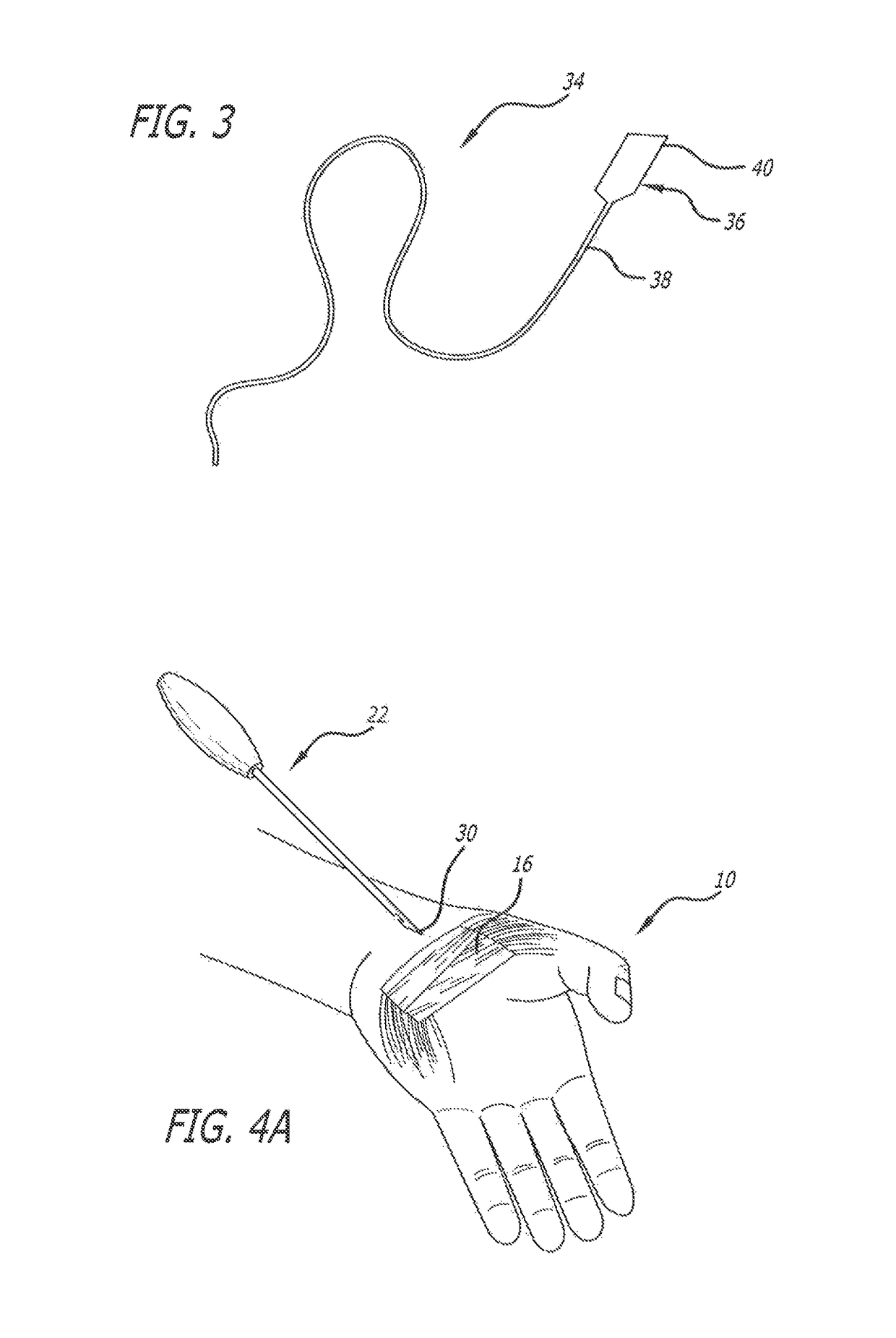
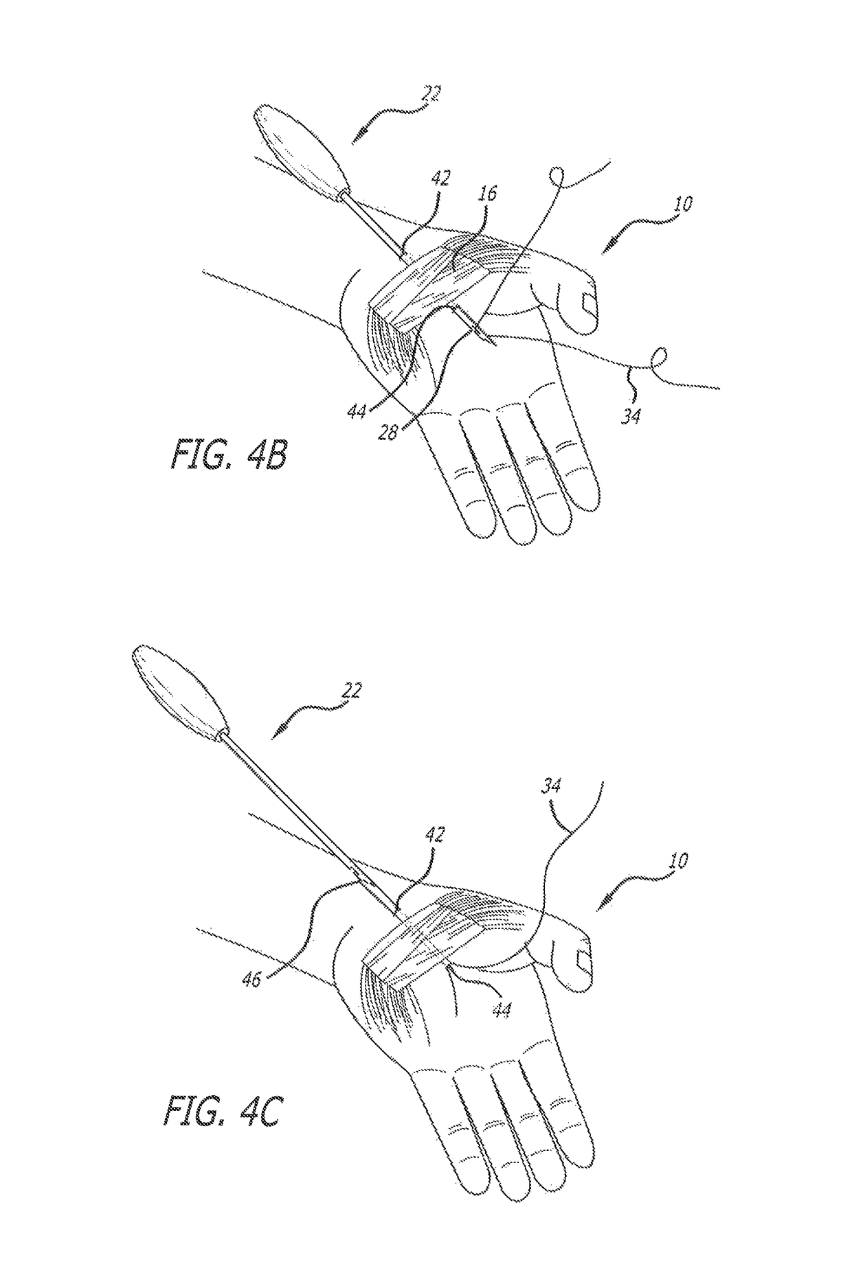
[0038]The present invention provides for the minimally invasive transection of tissue and obviates the need for scalpels, saws or endoscopes. The invention is especially applicable for the transection of ligaments and most particularly, for the release of the transverse carpal ligament in the treatment of carpal tunnel syndrome.

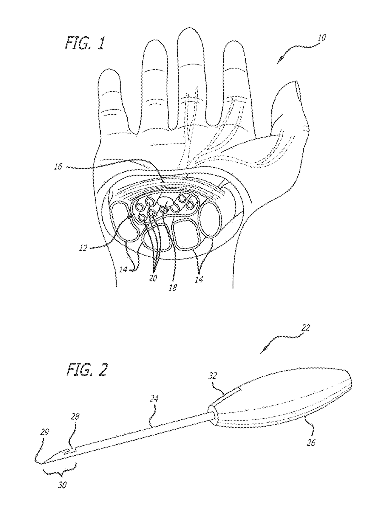
[0039]FIG. 1 is a cross-sectional view of the carpal tunnel area of the hand 10. The carpal tunnel 12 is the area of the wrist and palm of the hand 10 formed by a U-shaped cluster of bones 14 that form a hard floor and two walls of the tunnel. The roof of the tunnel is formed by the transverse carpal ligament 16 which attaches to the wrist bones. Within the confines of the tunnel is the median nerve 18 and the flexor tendons 20 of the thumb and fingers. Carpal tunnel syndrome is caused by a compression of the median nerve by either a decrease in the size of the tunnel or an increase in the size of its contents. Such pressure may be relieved by a release of th...


PUM


Abstract

A method and apparatus for transecting soft tissue, such as a ligament, and more particularly, the transverse carpal ligament. A pair of hollow introducer needles can be used to rout a thread-like, smooth and non-abrasive cutting element around tissue, such as a soft tissue, to enable a transection of the soft tissue using minimally invasive techniques. The cutting element is routed into position about the target soft tissue such that the cutting element both enters and exits the body from the same side of the soft tissue. The smooth and non-abrasive exterior surface of the cutting element serves to provide a kerf-less cut.

Description

CROSS-REFERENCES TO RELATED APPLICATIONS[0001]This application is a continuation-in-part of U.S. Ser. No. 13 / 870,291, filed on Apr. 25, 2013, incorporated by reference herein in its entirety, which is a continuation-in-part of U.S. Ser. No. 13 / 460,246, filed on Apr. 30, 2012, incorporated by reference herein in its entirety.[0002]The present invention is generally directed to surgical methods for the transection, by minimally invasive means, of soft tissue such as, for example, the transverse carpal ligament that is commonly released as a treatment for carpal tunnel syndrome.BACKGROUND[0003]Many people suffer from injury to the soft tissues of the wrist and carpal tunnel, often caused by frequent, sustained repetitive motion involving the hands. Repetitive activities which require the same or similar hand / wrist action can result in injuries which have been collectively referred to as Cumulative Repetitive Stress Syndrome or Repetitive Strain Injury. The most familiar and common of s...

Claims


Application Information

Patent Timeline
Patent Type & Authority Patents(United States)
IPC IPC(8): A61B17/32A61B17/3205A61B17/34A61B17/14A61B17/3207
CPCA61B17/320036A61B17/149A61B17/3205A61B17/34A61B17/3403A61B17/32053A61B2017/320733A61B2017/32006A61B2017/00349A61B2017/00473A61B2017/320028A61B2017/3405
Inventor GUO, JOSEPHGUO, DANZHUGUO, DANQING
Owner GUO JOSEPH
Why Eureka
Try Eureka