Coating process for microfluidic sample arrays

a microfluidic array and coating technology, applied in chemical/physical/physicochemical processes, chemical apparatus and processes, laboratories, etc., can solve the problems of inability to properly load the microfluidic array with samples, difficult to transfer large collections of fluid samples such as tissue samples stored in older style 96- or 384-well plates into more efficient high density arrays of nanoliter receptacles, and difficult to prepare and process nanoliter chips. complex and time-consuming, the effect o

Active Publication Date: 2019-02-26
LIFE TECH CORP
View PDF191 Cites 2 Cited by
  • Summary
  • Abstract
  • Description
  • Claims
  • Application Information

AI Technical Summary

Benefits of technology

The patent describes a method for controlling the surface modification of a chipset that can hold microfluidic samples. The process involves using a camera to align the chip with a reference point, and then dispensing a liquid with a specific algorithm to fit into the chip. This allows for easy loading of different fluids into the chip for coating or modification. The process also includes a novel technique for forcing the chip into position using a low surface tension fluid, and keeping it there while using a high surface tension fluid for carrying out the desired chemistry. The technical effects include improved accuracy and efficiency in the modification of microfluidic devices.

Problems solved by technology

However, nanoliter chips require complex time-consuming preparation and processing.
Transferring large collections of fluid samples such as libraries of small molecule drug candidates, cells, probe molecules (e.g., oligomers), and / or tissue samples stored in older style 96- or 384-well plates into more efficient high density arrays of nanoliter receptacles can be difficult.
Any misalignment of the pins to the through-holes on the chip will result in a failure to properly load the microfluidic array with sample.

Method used


Image

  • Coating process for microfluidic sample arrays
  • Coating process for microfluidic sample arrays
  • Coating process for microfluidic sample arrays

Examples


example 1

[0266]A surface exposes a carboxylic acid moiety. A solution is prepared with 6-arm polyethylene glycol terminated with —NH2 and —COOH each and (1-Ethyl-3-[3-dimethylaminopropyl]carbodiimide hydrochloride). The carboxylic acid-containing surface is exposed to the solution of polyethylene glycols. If necessary, the solution can be dried on the surface and incubated at elevated temperature to improve the yield of cross-linking between amine and carboxylic acid groups. The resulting surface should show a thick, covalently-attached PEG film.

[0267]Formation of Thick Films of Polyelectrolytes by Layer-to-Layer Adsorption

[0268]A surface is exposed to a solution of polycations and polyanions sequentially. By electrostatic attraction, a film of polycation / polyanion is formed on the surface.

[0269]Differential Coating from Hydroxyl-Terminated Surface

[0270]The exterior and interior surfaces of OpenArray chip are uniformly coated with a film exposing hydroxyl groups. Then, the chip is treated wi...

example 2

[0283]The chip is coated with a hydrophobic silane and a photomask is placed over the chip such that light may only access the interior of the channels. This assembly is exposed to a high energy UV light. The assembly may be subjected to a flow of oxygen to create reactive oxygen species. The combination of light and reactive oxygen cleans the exposed surfaces rendering them hydrophilic and capable of being further derivatized.

example 3

[0284]The chip is coated with a hydrophilic silane such as a PEG silane and a set of photomasks is placed over the chip such that light may only access the exterior surfaces of the array. The array is then exposed to a hydrophobic silane to create the patterned array.

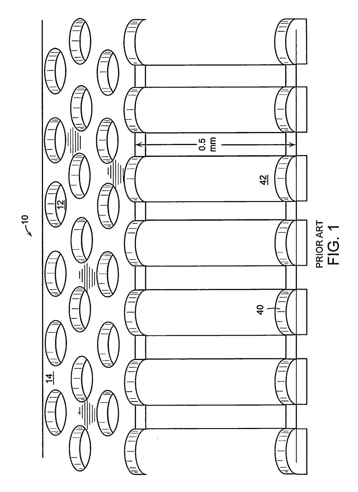
[0285]In such a process, patterned substrates of metal, particularly stainless steel chips, are created through the process of photochemically etching from both sides. This two-sided etching of the through-hole walls creates an hourglass shape for the through-holes, when viewed in cross-section. The resulting “throat” created in the metal chip may be employed for advantage in that one may differentially react, or treat, parts of the channel interior. For example, the top half of the channel could be left hydrophobic, and the bottom half cleaned to become hydrophilic, then optionally coated with a PEG silane. Alternately, a silane with a photoactivated linker moiety may be employed to create reactivity toward a modifying...


PUM

PropertyMeasurementUnit
volumesaaaaaaaaaa
spacingaaaaaaaaaa
diameteraaaaaaaaaa

Abstract

A differentially coated device for conducting a plurality of nano-volume specified reactions, the device comprising a platen having at least one exterior surface modified to a specified physicochemical property, a plurality of nano-volume channels, each nano-volume channel having at least one interior surface in communication with the at least one exterior surface that is selectively coated with an optionally dissolvable coating agent physisorbed to at least one interior surface, wherein the optionally dissolvable coating agent comprises a coating agent and a first component for the plurality of specified reactions. Methods for preparing and using such devices are also provided, as well as a method of registering a location of a dispenser array in relation to a microfluidic array. A first one of the dispenser array and the microfluidic array is movable in relation to the frame, and the other of the first one of the dispenser array and the microfluidic array is fixed relative to the frame. Quantities related to a vector displacement from the alignment position to a fixed position on the one of the dispenser array and the microfluidic array is determined. The quantities thus determined are used to guide positioning of the dispenser array relative to the microfluidic array.

Description

CROSS-REFERENCE TO RELATED APPLICATIONS[0001]This application is a continuation of U.S. application Ser. No. 11 / 198,882 filed Aug. 4, 2005, and claims priority to U.S. application No. 60 / 608,231, filed Sep. 9, 2004, and claims priority to U.S. application No. 60 / 599,217, filed Aug. 4, 2004, which disclosures are herein incorporated by reference in their entirety.TECHNICAL FIELD[0002]The present invention relates to techniques for transferring small volumes of liquid, and more specifically to calibration of dispensers relative to nanoliter sample volumes in an array. The present invention also relates to processes and the devices for spatially selective chemical modification or coating of the surfaces of a substrate or through-hole array plate, such as may be used in microfluidic or nanofluidic storage and analysis systems or other applications.BACKGROUND ART[0003]Various systems are known for performing a large number of chemical and biological storage assays and synthesis operation...

Claims


Application Information

Patent Timeline
Patent Type & Authority Patents(United States)
IPC IPC(8): B01J19/00B01L3/00B01L3/02
CPCB01J19/0046B01L3/50857B01J2219/0059B01J2219/00596B01L2300/16B01L3/0244B01L3/5025B01L2200/12B01L2200/16B01J2219/00659
Inventor BRENAN, COLIN J. H.CHO, JAMIEGARCIA, JAVIERHESS, ROBERTKANIGAN, TANYA S.KATZ, ARRINKIM, NAMYONGLINTON, JOHNSRIVASTAVA, SHAILESHYODER, KARL
Owner LIFE TECH CORP
Why Eureka
Try Eureka