Over-temperature protection system of a charging device

a charging device and over-temperature protection technology, applied in the direction of battery over-heat protection, safety/protection circuits, transportation and packaging, etc., can solve the problem of power circuit interruption to stop charging, and achieve the effect of avoiding damage to the charging plug caused by abnormal temperatur

Active Publication Date: 2019-03-05
JIANGYIN SINBON ELECTRONICS
View PDF2 Cites 1 Cited by
  • Summary
  • Abstract
  • Description
  • Claims
  • Application Information

AI Technical Summary

Benefits of technology

[0004]An objective of the present invention is to provide an over-temperature protection system of a charging device to sense a variation of the temperature of a charging plug. When the temperature of the charging plug is abnormal, a power circuit is interrupted to stop charging. Therefore, the damage of the charging plug caused by abnormal temperature is avoided.

Problems solved by technology

When the temperature of the charging plug is abnormal, a power circuit is interrupted to stop charging.

Method used


Image

  • Over-temperature protection system of a charging device
  • Over-temperature protection system of a charging device
  • Over-temperature protection system of a charging device

Examples


Embodiment Construction

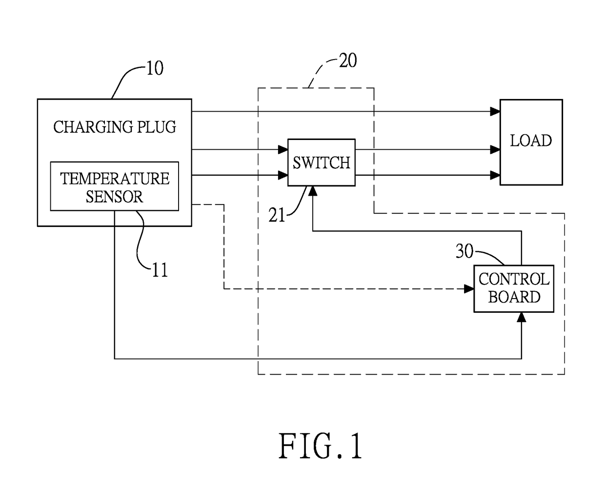
[0012]With reference to FIG. 1, an over-temperature protection system comprises a temperature sensor 11, a switch 21 and a control board 30.

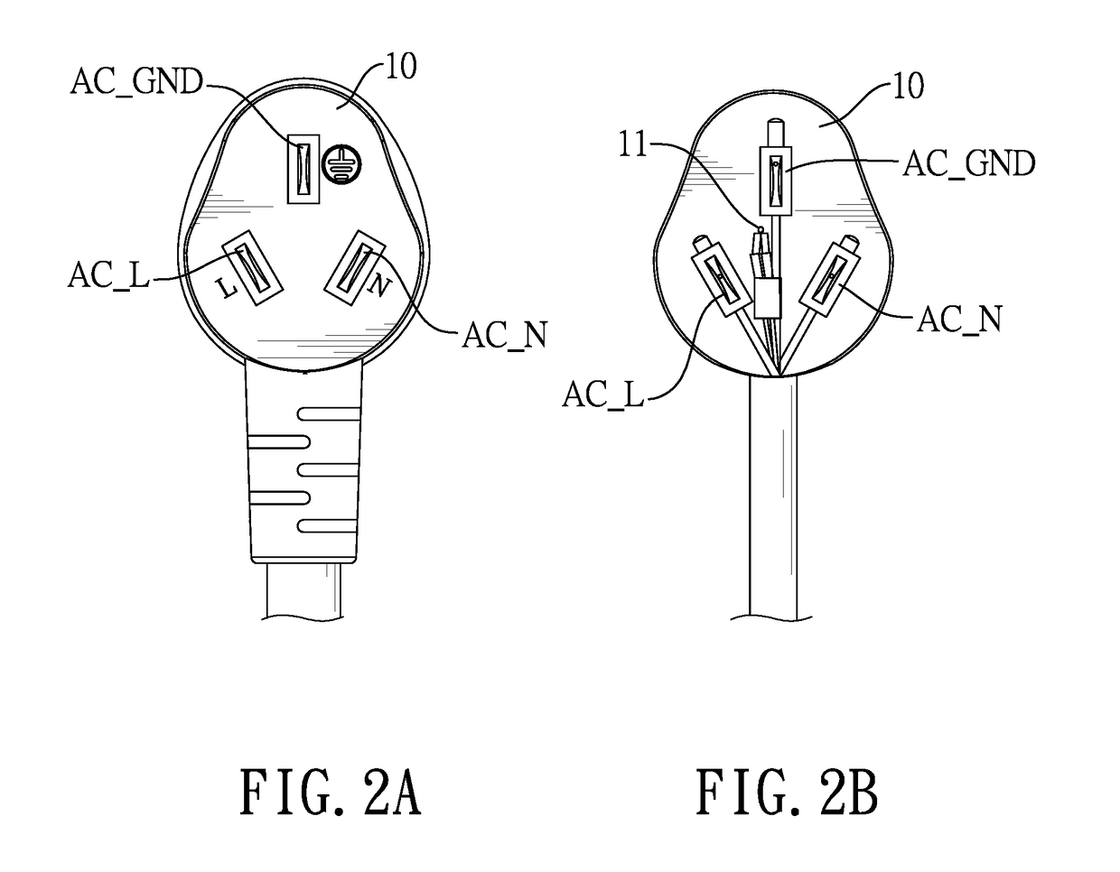
[0013]The temperature sensor 11 is mounted in a charging plug 10 connected to a charging device 20 that gets power through a power circuit. With reference to FIGS. 2A and 2B, the charging plug 10 is an alternating current (AC) plug. In this embodiment, the charging plug 10 is a three-phase plug having three pins, AC_GND, AC_L and AC_N. In this embodiment, the temperature sensor 11 may be a thermistor and coupled between the AC_L and the AC_N. In one embodiment, the temperature sensor 11 is mounted in the charging plug 10 by injection molding technique.

[0014]The switch 21 is connected to the power circuit between the charging plug 10 and the charging device 20 to control the conduction of the power circuit. In this embodiment the switch 21 is a relay having two contacts and a control terminal. The control terminal is connected to the control boar...


PUM


Abstract

An over-temperature protection system has a control board mounted in a charging device and a temperature sensor mounted in a charging plug. A switch is coupled on a power circuit of the charging plug and controlled by the control board. When the charging plug is connected to a power supply and the charging device begins a charging operation, the control board periodically receives temperature information of the charging plug sensed by the temperature sensor. When the control board determines that the temperature of the charging plug is abnormal, the switch is open to interrupt the power circuit so as to stop the charging operation for ensuring safety of the charging device.

Description

BACKGROUND OF THE INVENTION1. Field of the Invention[0001]The present invention relates to an over-temperature protection system, especially an over-temperature protection system of a charging device.2. Description of the Prior Arts[0002]Energy saving and emission reduction are receiving increasing attention with the impact on the earth's atmosphere caused by carbon dioxide emissions leading to greenhouse effect and other abnormal climate changes. Reducing the carbon dioxide emissions in order to ameliorate climate change has especially become the primary policy for every government all over the world and is strongly advocated by the governments. Therefore the automobile manufacturers have developed the electric vehicles that are making vehicles cleaner, more fuel efficient, and reduce the carbon dioxide emissions for responding to the governmental policy. And the electric vehicles have become one of the top choices of the drivers for reducing the fuel expense.[0003]A conventional c...

Claims


Application Information

Patent Timeline
Patent Type & Authority Patents(United States)
IPC IPC(8): H02J7/00H02J7/04H02M1/32H02H5/04
CPCH02H5/047H02H5/043H02J7/0031H02J7/047H02M1/32H02J7/0047H02M2001/327H02J2007/005H02J7/0088H02J7/0048H02J7/007192H02J7/00309H02J7/04H02M1/327
Inventor ZHANG, XUE-FENGDU, HAI-YUNLI, DONG-JIANGLIU, YA-JUNGU, JING-JUN
Owner JIANGYIN SINBON ELECTRONICS
Why Eureka
Try Eureka