Apparatus for transmitting data in interleave division multiple access (IDMA) system
a technology of interleave division and multiple access, applied in the direction of digital transmission, code conversion, coding, etc., can solve the problems of increasing the burden on the transmitter and the system, memory shortage and delay or the like, and the concern of the same problems, so as to achieve the effect of more flexible data transmission
- Summary
- Abstract
- Description
- Claims
- Application Information
AI Technical Summary
Benefits of technology
Problems solved by technology
Method used
Image
Examples
first example
(a-1) First Example
[0366]As a first example, c(i) which is the value of an i-th bit of an output sequence is expressed as follows.
[0367]c(i)=bimodNCB(floor(iNCB))[Math.5]
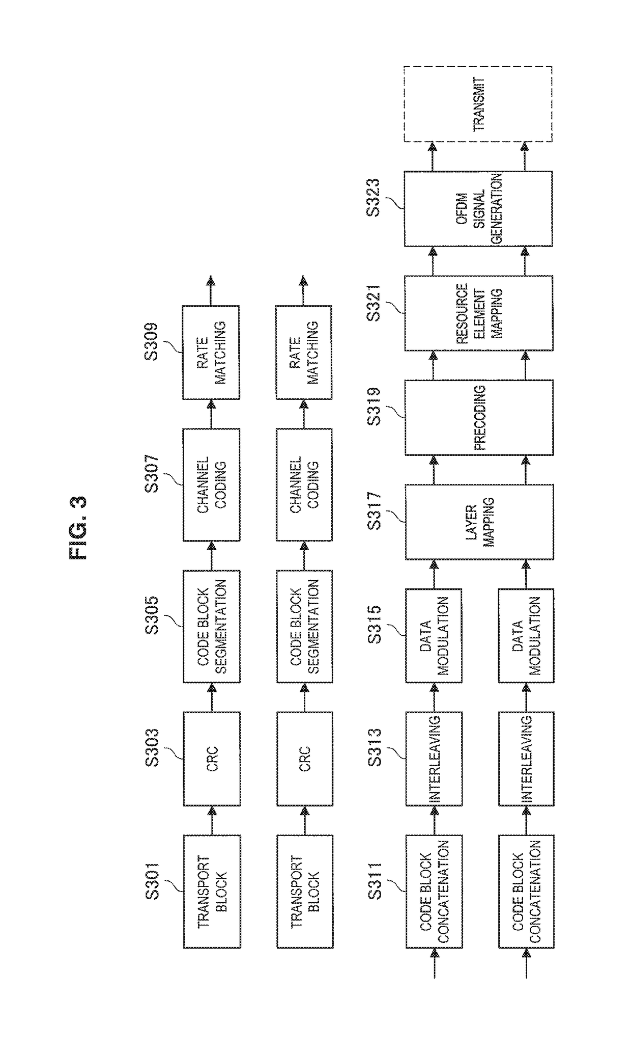
[0368]NCB is the number of code blocks. Further, bj(k) is the value of a k-th bit in a bit sequence of a j-th code block. An index i is in the range of 0 to LCB*NCB−1 and LCB is the length of a code block. Hereinafter, a specific example will be described with reference to FIG. 23.
[0369]FIG. 23 is an explanatory diagram illustrating the first example of code block concatenation according to the fourth embodiment. Referring to FIG. 23, sequences of three code blocks (code blocks 0, 1, and 2) are illustrated. The sequences of the three code blocks are concatenated to generate a codeword. In the codeword, three bit sets including bits of code blocks 0, 1, and 2 are disposed in order. That is, in the codeword, the three bit sets including b0(k), b1(k), and b2(k) are disposed in order of the index k. The index k ...
second example
(a-2) Second Example
[0370]As a second example, an output sequence c(i) may be expressed as follows.
[0371]c(i)=bfloor(iLCB)(imodLCB)[Math.6]
[0372]As described above, bj(k) is the value of a k-th bit in a bit sequence of a j-th code block. LCB is the length of a code block. The index i is in the range of 0 to LCB*NCB−1. LCB is the number of code blocks. Hereinafter, a specific example will be described with reference to FIG. 24.
[0373]FIG. 24 is an explanatory diagram illustrating the second example of the code block concatenation according to the fourth embodiment. Referring to FIG. 24, sequences of three code block (code blocks 0, 1, and 2) are illustrated. The three code blocks are concatenated to generate a codeword. In the codeword, code blocks 0, 1, and 2 are disposed in order.
(b) Bit Collection
[0374]Bit collection may be performed on the interleaved two or more code blocks. As a result, a codeword may be generated. The bit collection may be bit collection of exclusive OR...
application examples
9. Application Examples
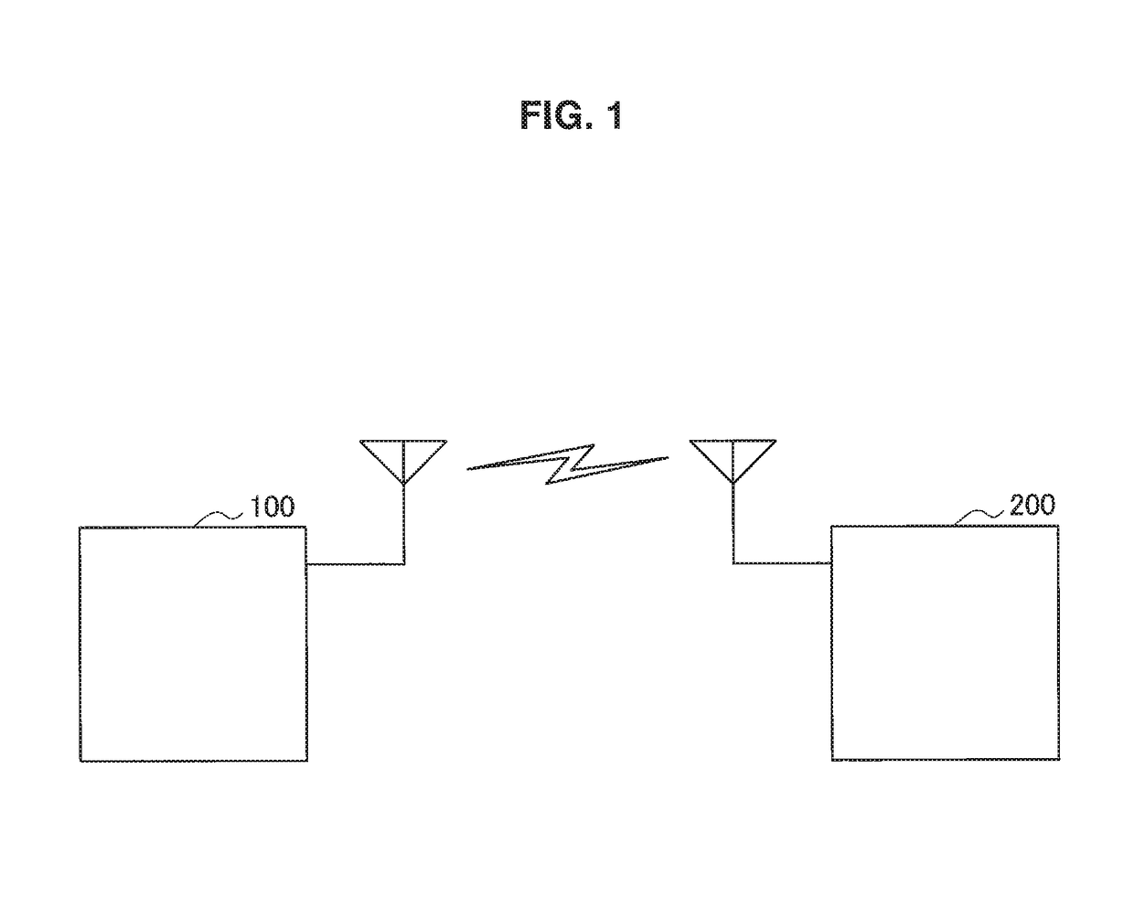
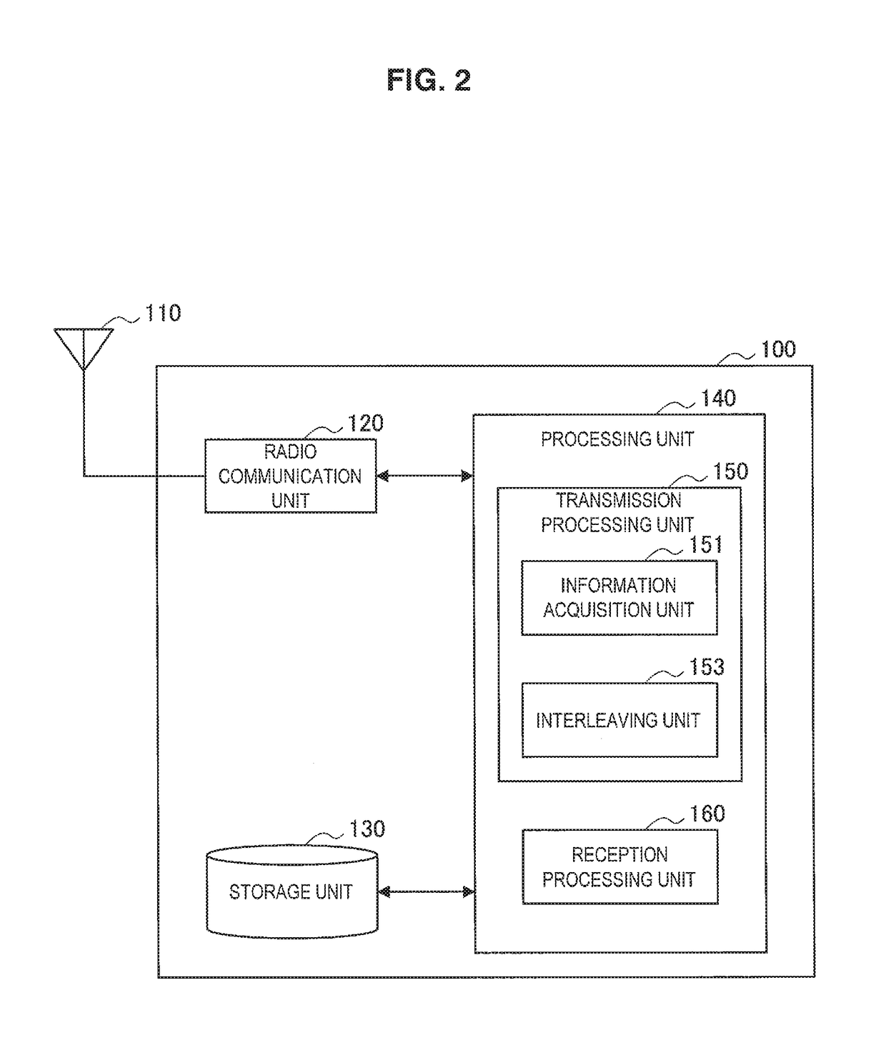
[0418]The technology of an embodiment of the present disclosure is applicable to various products. For example, the radio communication apparatus (the first radio communication apparatus 100 or the second radio communication apparatus 200) may be realized as any type of evolved Node B (eNB) such as a macro eNB or a small eNB. A small eNB may be an eNB that covers a cell smaller than a macro cell, such as a pico eNB, micro eNB, or home (femto) eNB. Instead, the radio communication apparatus may be realized as any other types of base stations such as a NodeB and a base transceiver station (BTS). The radio communication apparatus may include a main body (that is also referred to as a base station apparatus) configured to control radio communication, and one or more remote radio heads (RRH) disposed in a different place from the main body. Additionally, various types of terminals to be discussed later may also operate as the radio communication apparatus by tempor...
PUM
 Abstract
Description
Claims
Application Information
 - R&D
- Intellectual Property
- Life Sciences
- Materials
- Tech Scout
- Unparalleled Data Quality
- Higher Quality Content
- 60% Fewer Hallucinations
Browse by: Latest US Patents, China's latest patents, Technical Efficacy Thesaurus, Application Domain, Technology Topic, Popular Technical Reports.
© 2025 PatSnap. All rights reserved.Legal|Privacy policy|Modern Slavery Act Transparency Statement|Sitemap|About US| Contact US: help@patsnap.com


