Systems and methods for mapping DMRS configuration to phase noise tracking pilot for improved receiver performance

Active Publication Date: 2019-03-12
TELEFON AB LM ERICSSON (PUBL)
View PDF4 Cites 7 Cited by
  • Summary
  • Abstract
  • Description
  • Claims
  • Application Information

AI Technical Summary

Benefits of technology

The patent text describes methods and systems for improving the performance of receivers in wireless communication. The technical effect of the patent is to reduce the overhead of transmitting a pilot signal for phase noise tracking, which can lead to a reduction of up to 75% in overhead for some configurations. This can increase the efficiency of the communication and improve the overall performance of the receiver.

Problems solved by technology

One may observe that these signals are not intended to provide a very accurate synchronization, neither in time nor in frequency.
However, the always-on signals add some complexity to the radio system, result in bad energy performance, and provide constant interference.
A problem with these designs is that the sync-procedure becomes more complicated and overhead increases.
For example, phase noise tracking RSs may use a large fraction of the spectrum at the cost of decreased data rates.
As another example, reusing DMRS is inefficient as the needed time-density is high for accurate phase noise tracking.
Thus, if the same signal is used for both demodulation and phase noise tracking, unnecessary high overhead may be created.

Method used


Image

  • Systems and methods for mapping DMRS configuration to phase noise tracking pilot for improved receiver performance
  • Systems and methods for mapping DMRS configuration to phase noise tracking pilot for improved receiver performance
  • Systems and methods for mapping DMRS configuration to phase noise tracking pilot for improved receiver performance

Examples


Embodiment Construction

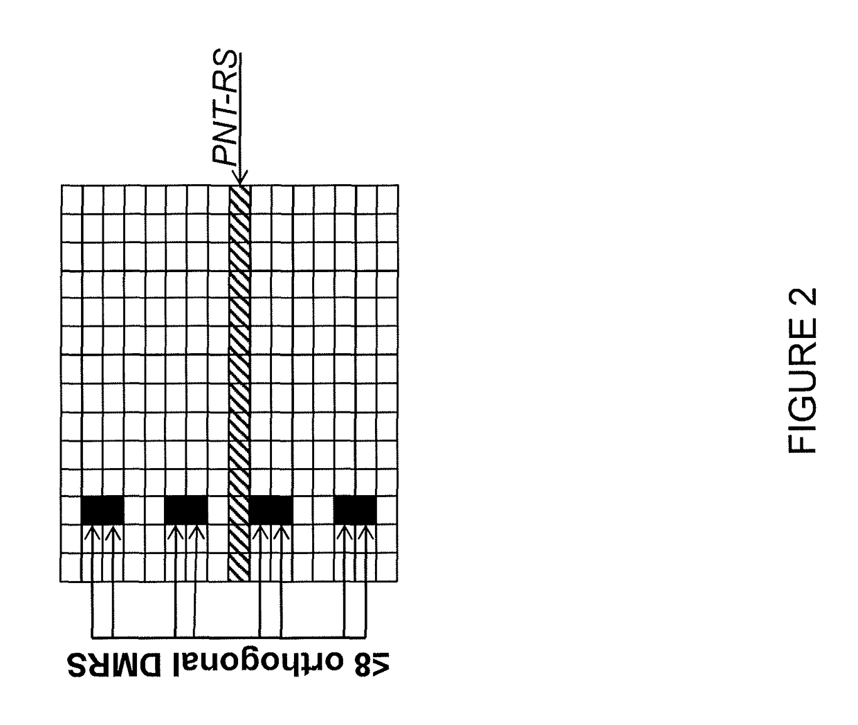
[0041]According to certain embodiments, how the PNT-RS is beam-formed in relation to the DMRS may be implicitly or explicitly signaled. For example, the phase noise tracking reference signal (PNT-RS) may be mapped to at least one specific port on the DMRS. For example, in a particular embodiment, the phase noise tracking reference signal may be mapped to the first DMRS port. As such, the receiver may know that the channel estimate of the effective channel for said DMRS port represents the effective channel used to transmit the PNT-RSs. This enables a receiver and corresponding transmitter to optimize the beam-forming of said port to enable a good reception by the receiver. In certain embodiments, the receiver may exploit this optimized beam-forming as the DMRS for different users / layers are orthogonal and have higher processing gain than the PNT-RS, which is transmitted with low density to avoid too large over-head and potentially, in some embodiments, independent estimates are need...


PUM


Abstract

According to certain embodiments, a user equipment (810) is provided for use in a cellular network. The user equipment (810) may include a transceiver (910), a processor (920), and a memory (930). The user equipment (810) may be configured to acquire a Demodulation Reference Signal (DMRS) configuration. A mapping is determined from the DMRS configuration to a phase noise tracking reference signal (PNT-RS). A channel estimate is performed using the DMRS configuration. Phase noise estimation and compensation is performed based on the PNT-RS by using the mapping and the channel estimate.

Description

PRIORITY[0001]This non-provisional application is a U.S. National Stage Filing under 35 U.S.C. § 371 of International Patent Application Serial No. PCT / SE2017 / 050119 filed Feb. 8, 2017, and entitled “Systems and Methods for Mapping DMRS Configuration to Phase Noise Tracking Pilot for Improved Receiver Performance” which claims priority to U.S. Provisional Application No. 62 / 292,921 filed on Feb. 9, 2016, both of which are incorporated herein by reference.TECHNICAL FIELD[0002]The present disclosure relates, in general, to wireless communications and, more particularly, to mapping DMRS configuration to phase noise tracking pilot for improved receiver performance.BACKGROUND[0003]Communications between a transmitter and receiver generally require some form of synchronization in time and / or frequency before transmissions of messages can be received reliably. In cellular systems such as Long Term Evolution (LTE), base stations regularly broadcast narrowband synchronization signals regular...

Claims


Application Information

Patent Timeline
IPC IPC(8): H04L5/00H04L27/26H04L25/02
CPCH04L5/0051H04L5/0007H04L27/2675H04L27/266H04L27/2613H04L25/0226H04L25/0224H04L27/2695H04L5/00
Inventor HESSLER, MARTINBALDEMAIR, ROBERTLINDBOM, LARSSAHLIN, HENRIK
Owner TELEFON AB LM ERICSSON (PUBL)
Why Eureka
Try Eureka