Advanced continuous analyte monitoring system

a continuous analyte and monitoring system technology, applied in the field of processing, transmitting and displaying data received from analyte sensors, can solve the problems of diabetes likely, diabetic will not know if his blood glucose value is going up (lower) or down (lower) based on conventional methods

Active Publication Date: 2019-03-19
DEXCOM
View PDF25 Cites 581 Cited by
  • Summary
  • Abstract
  • Description
  • Claims
  • Application Information

AI Technical Summary

Problems solved by technology

In the diabetic state, the victim suffers from high blood sugar, which causes an array of physiological derangements (kidney failure, skin ulcers, or bleeding into the vitreous of the eye) associated with the deterioration of small blood vessels.
Conventionally, a diabetic person carries a self-monitoring blood glucose (SMBG) monitor, which typically requires uncomfortable finger pricking methods.
Unfortunately, these time intervals are spread so far apart that the diabetic will likely find out too late, sometimes incurring dangerous side effects, of a hyperglycemic or hypoglycemic condition.
In fact, it is not only unlikely that a diabetic will take a timely SMBG value, but additionally the diabetic will not know if his blood glucose value is going up (higher) or down (lower) based on conventional methods.

Method used


Image

  • Advanced continuous analyte monitoring system
  • Advanced continuous analyte monitoring system
  • Advanced continuous analyte monitoring system

Examples


first embodiment

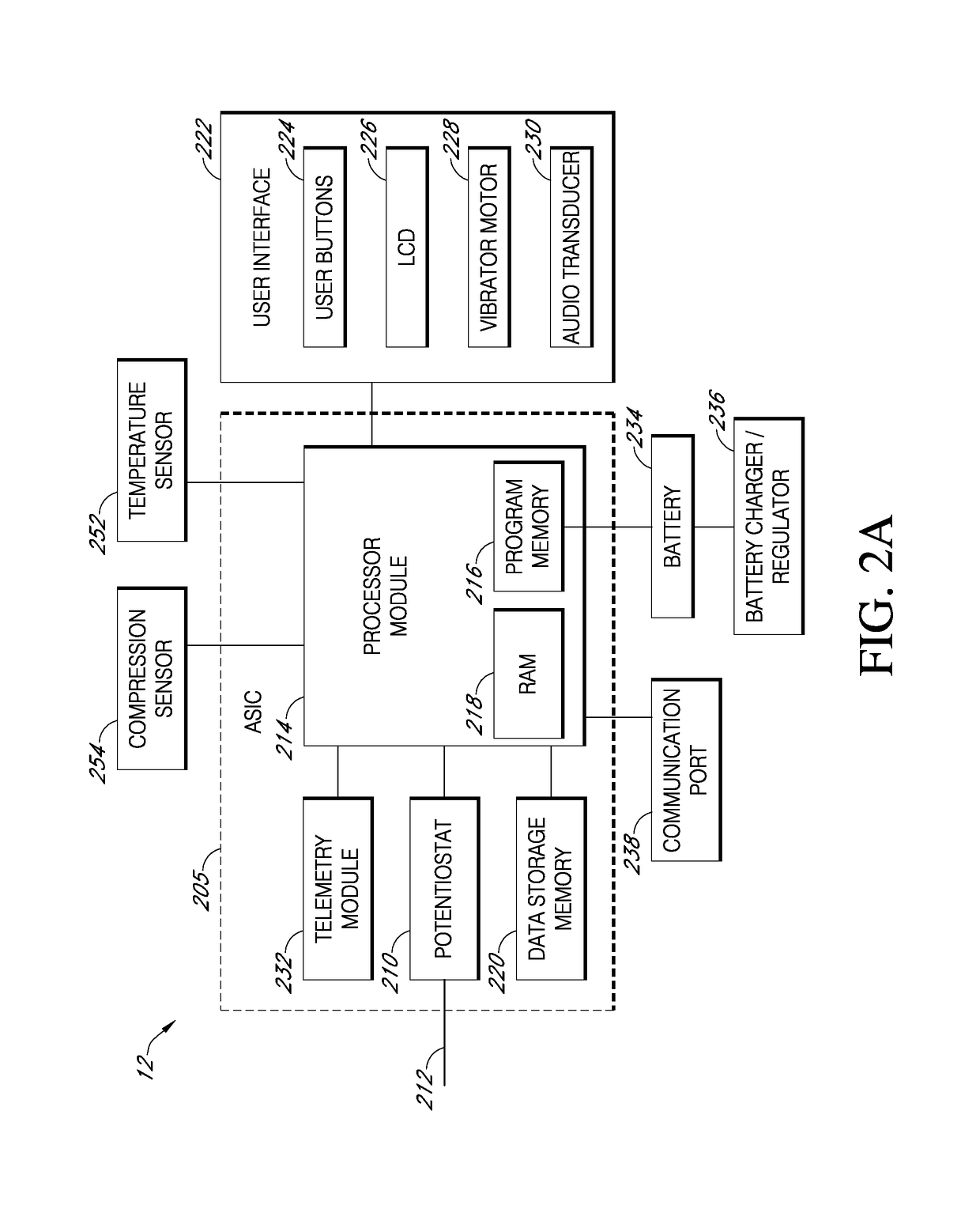
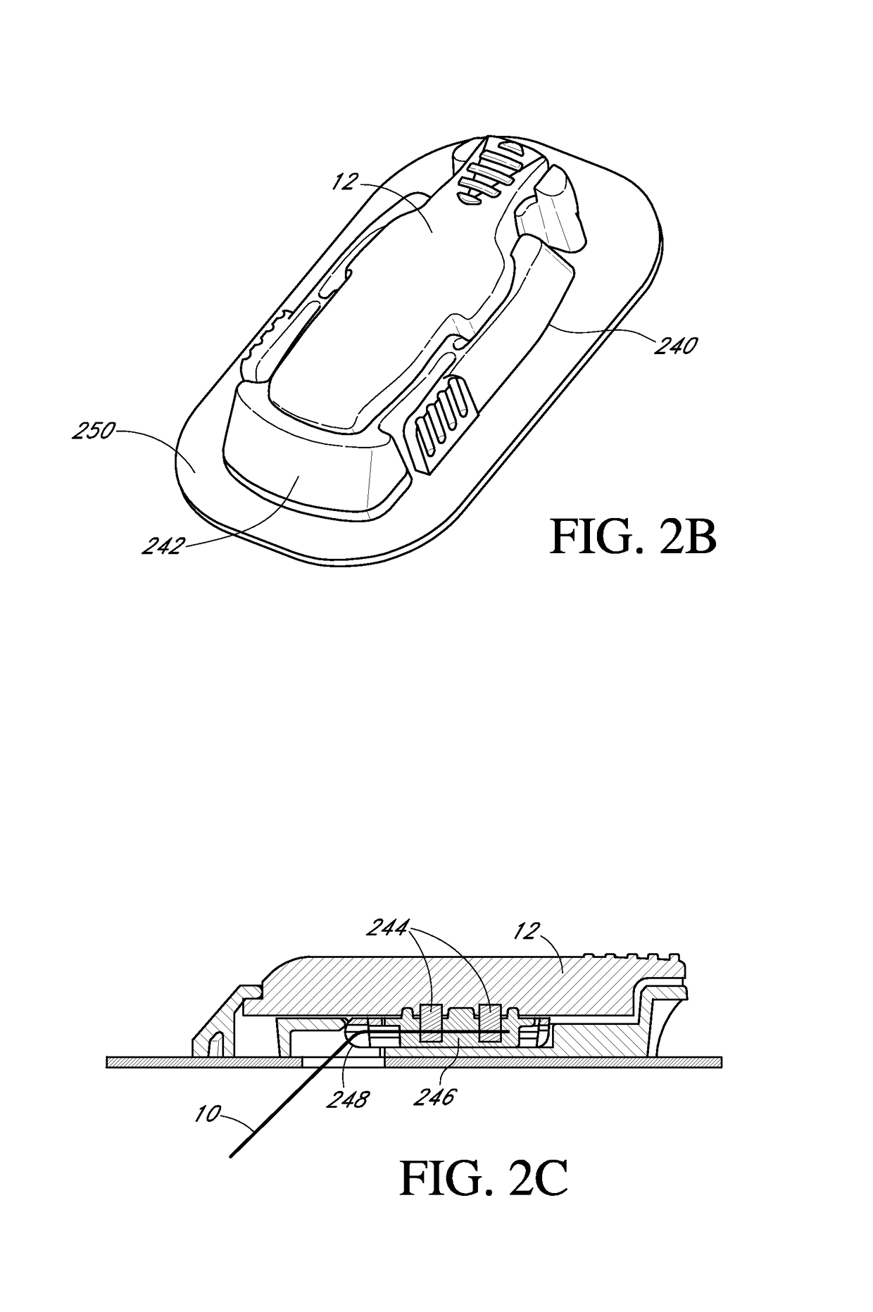
[0281]FIG. 13 illustrates sensor electronics module 12 including a pressure sensor configured to detect compression in proximity to an implanted sensor. Here, an outside housing of sensor electronics module 12 can include a rigid base 1300, a rigid cover 1302 and a compressible gasket 1304 between the base and cover. The housing can define an interior portion in which a printed circuit board (PCB) 1306 is carried on the interior portion of the base 1300. The PCB 1306 can incorporate ASIC 205 of FIG. 2A, for example. A pressure sensor 1408 resides on PCB 1306 and a contact 1310 resides on an interior portion of cover 1302. Contacts 1312 extend through base 1300 and are electrically coupled to PCB 1308 so that PCB can be electrically coupled to sensor 10 and / or electronics of mounting unit 240, for example.

[0282]In use, a sufficient external force applied to cover 1302 (e.g., a force applied in a direction perpendicular to the base 1300) can cause contact 1310 to apply pressure on pre...

second embodiment

[0284]The second embodiment can also measure sufficient externally applied force to cover 1402. An exemplary detected force is illustrated as an arrow in FIG. 14. Pressure sensor 1408 can then measure the applied and output data indicative of the measured force PCB 1406 for processing and / or initiating one or more actions in the manned described above.

[0285]Note that the first and second embodiments include compression sensor 254 in sensor electronics unit 12. It is understood that a pressure sensor can instead or additionally be placed in another component of sensor system 8, such as in a mounting unit configured to hold sensor 10 and sensor electronics unit 12. In such an embodiment, the mounting unit can include a compressible portion of the housing of the mounting unit and the pressure sensor can be configured to measure a force applied to the compressible portion of the housing and output data representative of the detected force to sensor electronics unit 12.

[0286]In some embo...


PUM


Abstract

Systems and methods for processing, transmitting, and displaying data received from a continuous analyte (e.g., glucose) sensor are provided. A sensor system can comprise a sensor electronics module that includes power saving features, e.g., a low power measurement circuit that can be switched between a measurement mode and a low power mode, wherein charging circuitry continues to apply power to electrodes of a sensor during the low power mode. The sensor electronics module can be switched between a low power storage mode and a higher power operational mode via a switch, e.g., a reed switch or optical switch. A validation routine can be implemented to ensure an interrupt signal sent from the switch is valid. The sensor can be physically connected to the sensor electronics module in direct wireless communication with a plurality of different display devices.

Description

CROSS-REFERENCE TO RELATED APPLICATION[0001]This application claims the benefit under 35 U.S.C. § 119(e) of U.S. provisional application Ser. No. 61 / 387,793, filed Sep. 29, 2010, the disclosure of which is hereby expressly incorporated by reference in its entirety and is hereby expressly made a portion of this application.FIELD OF THE INVENTION[0002]The present invention relates generally to systems and methods for processing, transmitting and displaying data received from an analyte sensor, such as a glucose sensor.BACKGROUND OF THE INVENTION[0003]Diabetes mellitus is a disorder in which the pancreas cannot create sufficient insulin (Type I or insulin dependent) and / or in which insulin is not effective (Type 2 or non-insulin dependent). In the diabetic state, the victim suffers from high blood sugar, which causes an array of physiological derangements (kidney failure, skin ulcers, or bleeding into the vitreous of the eye) associated with the deterioration of small blood vessels. A ...

Claims


Application Information

Patent Timeline
Patent Type & Authority Patents(United States)
IPC IPC(8): G06F1/32A61B5/145G06F1/3203
CPCA61B5/14532G06F1/3203A61B5/1451A61B2562/02A61B2560/0209A61B2560/0214A61B5/14507A61B5/1468A61B5/14865G08C17/02G06F1/3287A61B5/14503A61B5/0002
Inventor BOHM, SEBASTIANDERVAES, MARKJOHNSON, ERICKAMATH, APURV ULLASLARVENZ, SHAWNLEACH, JACOB S.LIEU, PHONGMAHALINGAM, AARTHIMILLER, TOMNEALE, PAUL V.PRYOR, JACKPEYSER, THOMAS A.RONG, DAITINGSAN VICENTE, KENNETHSHARIATI, MOHAMMAD ALISIMPSON, PETER C.WIGHTLIN, MATTHEW
Owner DEXCOM
Why Eureka
Try Eureka