Supercharge Your Innovation With Domain-Expert AI Agents!

Communication connector

a technology of communication connectors and connectors, applied in the direction of coupling devices, two-part coupling devices, electrical equipment, etc., can solve the problems of signal reflection, suppress the reduction of communication quality, and reduce communication quality, so as to reduce communication quality, the effect of easy connection to each terminal

Active Publication Date: 2019-03-19
AUTONETWORKS TECH LTD +2
View PDF21 Cites 0 Cited by
  • Summary
  • Abstract
  • Description
  • Claims
  • Application Information

AI Technical Summary

Benefits of technology

The invention allows for easy bending and connection of wires to terminals by exposing the end part of the wire on the terminal side and not covering it with insulation coating. A second shield member is connected to the first shield member to suppress impedance changes and maintain communication quality. The wires may include a drain wire for grounding, and a twisted pair cable for noise reduction. The invention improves communication quality and reduces the influence of noise.

Problems solved by technology

It is concerned that signal reflection occurs to reduce communication quality at an impedance changing point.
This can suppress a situation where an impedance changes between a part covered with the insulation coating and the exposed part, and can suppress a reduction of communication quality.

Method used


Image

  • Communication connector
  • Communication connector
  • Communication connector

Examples


case 50

(Shield Case 50)

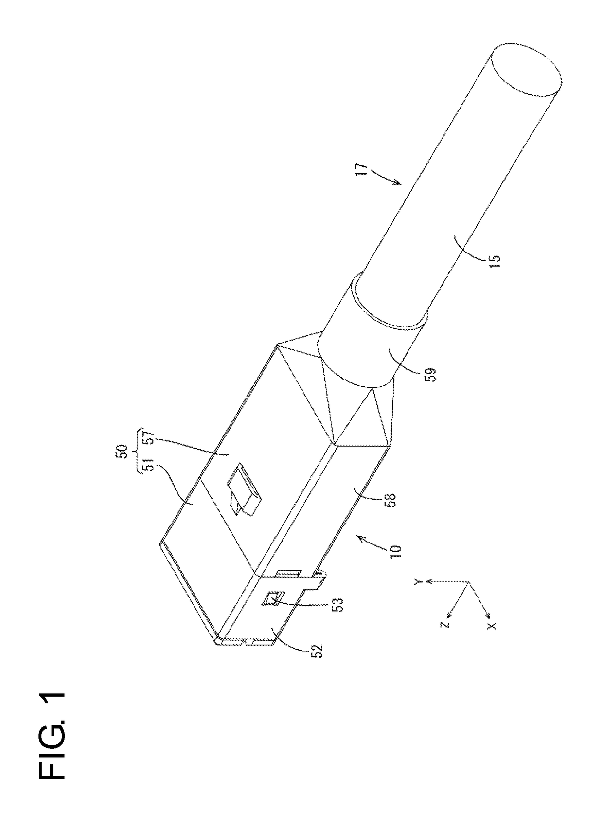
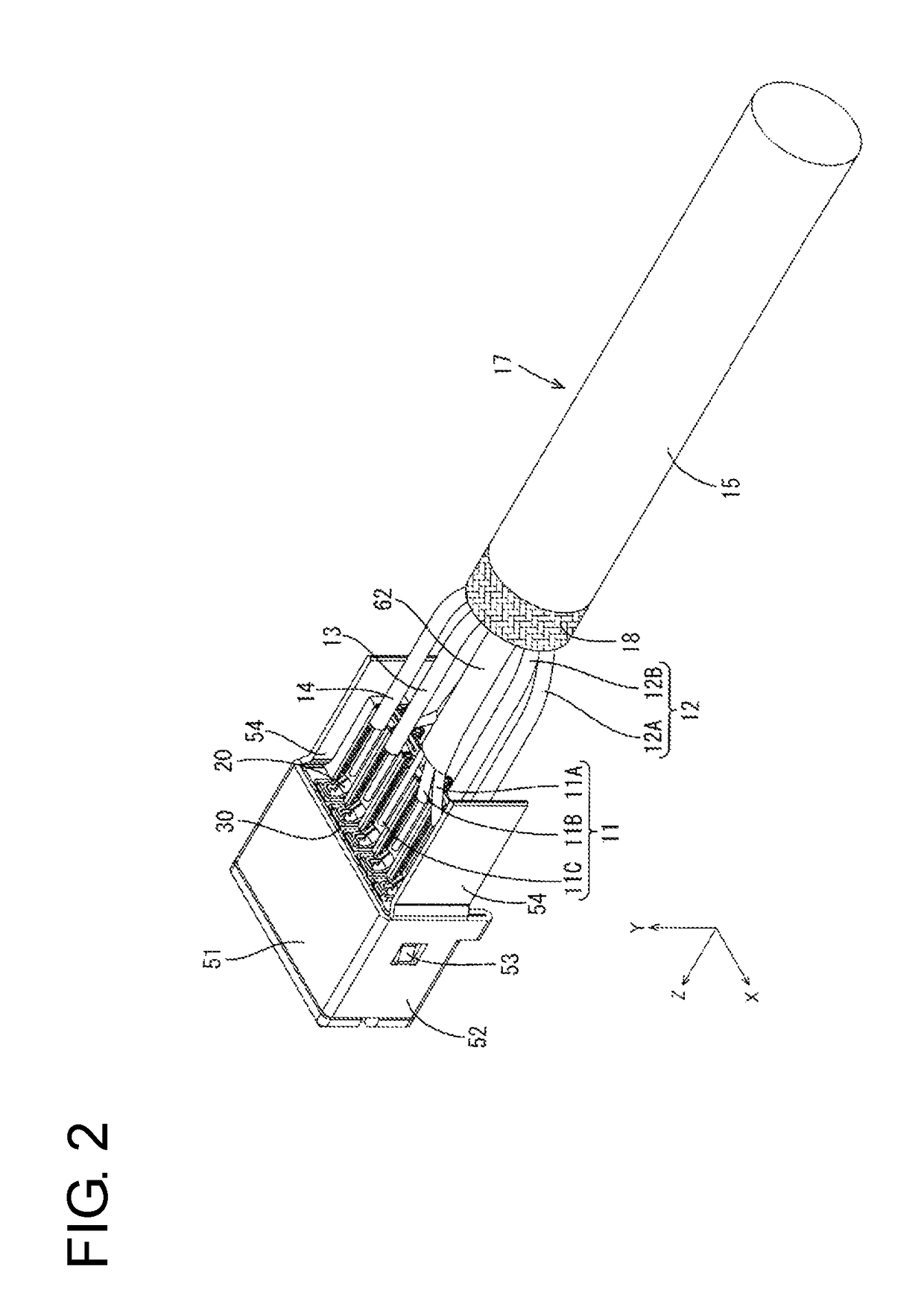
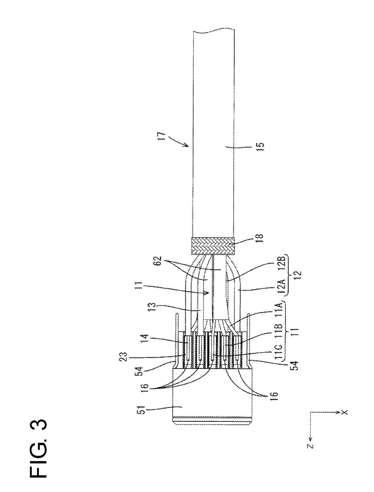
[0035]As shown in FIG. 1, the shield case 50 includes a first shield case 51 for covering the housing body 31 and a second shield case 57 disposed behind the first shield case 51 for covering the wires 11 to 14. Further, the shield case 50 is connected electrically to ground. The first shield case 51 is, for example, made of metal such as copper or copper alloy and, as shown in FIG. 2, includes a housing surrounding portion 52 in the form of a rectangular tube surrounding the housing 30 and connecting portions 54 to be connected electrically to the second shield case 57.

[0036]Resiliently deformable locked portions 53 are provided on left and right side surfaces of the housing surrounding portion 52. When the first shield case 51 is fit to the housing 30 from behind the housing 30, the locked portions 53 are locked to locking portions (not shown) formed by cutting side surfaces of the housing 30. The connecting portions 54 are plate-like parts extending rearward from ...


PUM


Abstract

A communication connector includes a wires (11, 12, 13, 14) for transmitting communication signals, terminals (20) to be connected to the respective wires (11, 12, 13, 14), a housing (30) for accommodating the terminals (20) and an insulation coating (15) for collectively covering the wires (11, 12, 13, 14). An end part of each wire (11, 12, 13, 14) on the side of the terminal (20) is exposed and not covered with the insulation coating (15). A conductive first shield member (61) is interposed between two adjacent wires (11A, 11B) and the insulation coating (15), and a conductive second shield member (62) surrounds exposed parts (19A, 19B) of the wires (11A, 11B). The first and second shield members (61, 62) are connected electrically.

Description

BACKGROUNDField of the Invention[0001]The invention relates to a communication connector.Description of the Related Art[0002]Japanese Unexamined Patent Publication No. 2008-507110 discloses an electrical connector capable of receiving four USB plug connectors. This electrical connector includes a housing and a plurality of electrical contacts bent into an L shape and made of metal.[0003]Some known electrical connectors are configured such that an end parts of wires are connected respectively to electrical contacts. Further, the wires collectively are surrounded by a shield layer and an insulation layer. In connecting such wires to the electrical contacts, the shield layer and the insulation coating need to be stripped at the end parts of the wires. This causes parts not covered with the shield layer to be formed at the end parts of the wires and an impedance changes with respect to parts covered with the shield layer. It is concerned that signal reflection occurs to reduce communica...

Claims


Application Information

Patent Timeline
Patent Type & Authority Patents(United States)
IPC IPC(8): H01R13/6593H01R13/6581H01R24/60
CPCH01R13/6593H01R24/60H01R13/6581
Inventor MAESOBA, HIROYOSHI
Owner AUTONETWORKS TECH LTD
Features
  • R&D
  • Intellectual Property
  • Life Sciences
  • Materials
  • Tech Scout
  • Unparalleled Data Quality
  • Higher Quality Content
  • 60% Fewer Hallucinations
Learn More