Telecommunication system for relaying cellular coverage

a cellular coverage and telecommunication system technology, applied in the field of telecommunication systems, can solve the problems of introducing additional constraints on the operation of base station entities, affecting the overall coverage, and low sinr (signal to interference plus noise ratio), so as to improve the coverage indoors, improve the link budget, and influence the overall coverage

Active Publication Date: 2019-03-26
VODAFONE IP LICENSING
View PDF69 Cites 2 Cited by
  • Summary
  • Abstract
  • Description
  • Claims
  • Application Information

AI Technical Summary

Benefits of technology

[0078]In certain cases, each candidate aggregator device may be a communication device that fulfils at least one criterion selected from: sufficient battery life; location within a portion of the given area of radio coverage for which the aggregator functionality is expected to be required; and current path loss metric for the communication link between the communication device and the cellular communication network falls below a path loss threshold.
[0145]Location services may also benefit from the availability and / or presence of aggregator devices as each aggregator may be used as a further means to discover the positions of respective communication devices, thereby improving location accuracy.

Problems solved by technology

Consequently, high levels of interference and low SINR (signal to interference plus noise ratio) can be expected near the cell edge.
The requirement for cellular communications coverage is far from uniform across a typical geographic area.
Furthermore natural features or features of the built environment introduce additional constraints upon the operation of base station entities.
These classes of base transceiver stations are typically used in areas where coverage would otherwise be inadequate or awkward to maintain using conventional eNB equipment.
The installation of fixed small cells by a network operator brings with it the burden of finding suitable locations, paying for the site rental, and deploying additional cables to connect the fixed Small Cells to other nodes of the network.
Furthermore, installation and commissioning (including configuring) of fixed small cells takes time: even if wireless backhaul is used instead of cables, the fixed small cells need to be installed in a suitable position and configured for operation at that location.
In addition, where the small cell device fails or otherwise requires servicing the device and the installation site needs to be accessible by the operator: since these devices are typically the property of the network operator but located on private land and in sometimes inaccessible locations, there are likely to be logistical and practical obstacles to intervention by one of the operator's engineers.
There are certain network conditions where individual communication devices in cellular networks have a disproportionately detrimental effect on the network performance.
Serving radio resources to communication devices at cell-edge has a higher cost in terms of resource allocation and power usage than a similar device in a region of the cell closer to a serving base transceiver station system (such as an eNodeB).
However, the numbers of communication devices and the demand for ever more network resources means that the network may be affected by capacity problems in the radio interface more often than is acceptable.
Network and other performance conditions very often change over time: for instance, individual communication devices that, by virtue of their location at the cell edge and active use of the network, have a detrimental effect on the network performance at one time, may, at other times, be idle and cause no such effect.
Although the LTE standards define the concept of a UE acting as a relay, implementing such a system within the LTE core network may be difficult.
The 3GPP standards require the LTE RAN to be modified to support devices acting as relays, which is undesirable for network operators.

Method used


Image

  • Telecommunication system for relaying cellular coverage
  • Telecommunication system for relaying cellular coverage
  • Telecommunication system for relaying cellular coverage

Examples


Embodiment Construction

[0170]The present disclosure relates to secure transport of UE data in a telecommunications network architecture that includes a radio access network (RAN), a core network (CN) and a packet data network (PDN). Communication devices, such as mobile terminals, user equipment (UEs) and wireless access stations, establish wireless connections to the network by means of the RAN.

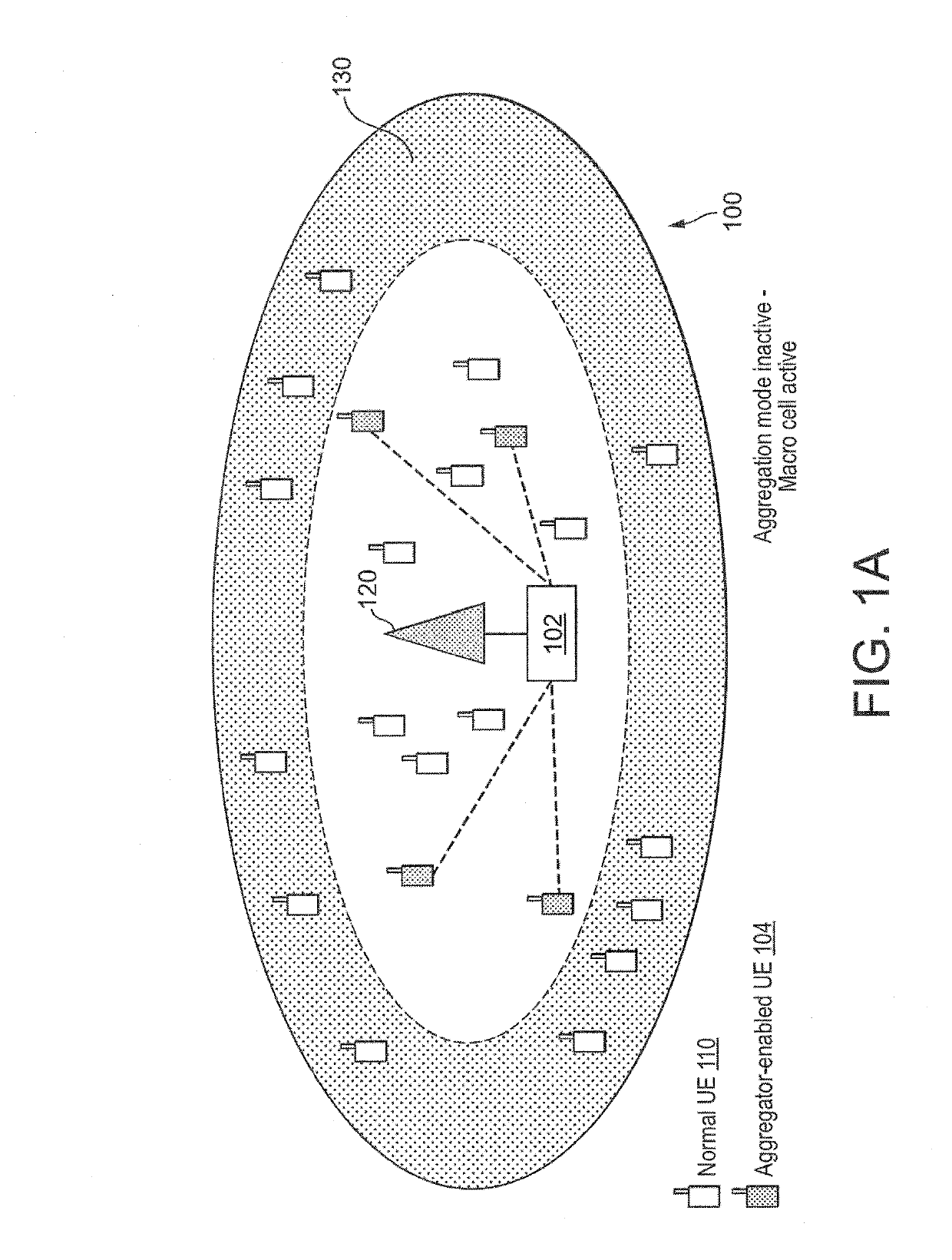
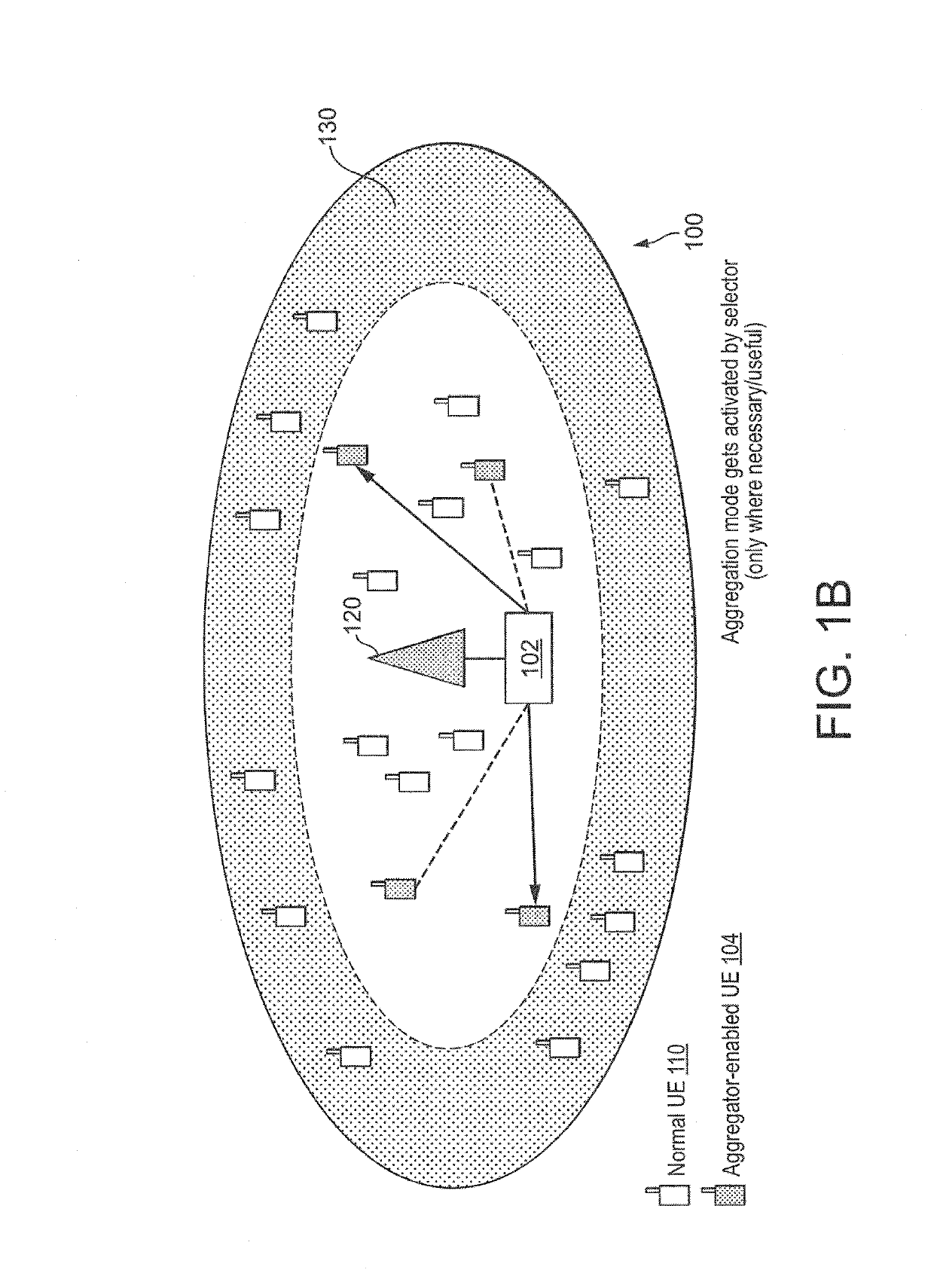
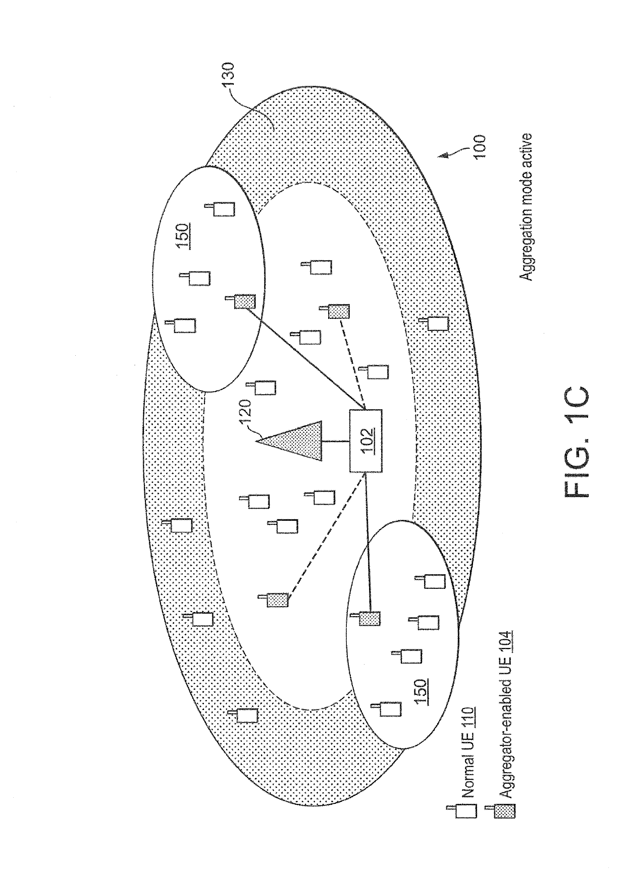
[0171]FIGS. 1A to 1C show a single cell 100 of the telecommunications network provided by a base transceiver station (i.e. macro eNB) 120 within the RAN. The telecommunications network architecture further comprises a network node, referred to as an aggregator controller (AC) 102, which communicates with the RAN and the CN (illustrated here as a link between the AC 102 and the eNB 120) but which may be implemented independently of the component entities of either RAN or CN.

[0172]The AC 102 identifies at least one communication device 104 as candidate for assignment as an aggregator. The AC 102 also instructs any g...


PUM


Abstract

A cellular telecommunications network architecture is described where certain UEs are configured to assist the network to improve coverage in regions of poor radio conditions. In certain embodiments, appropriate UEs are selected to act as a dynamic, out-of-band coverage extensions. Network performance can thereby be improved when serving users at the cell edge (or in other poor radio condition regions of a cell). Data from UEs connected to those assisting UEs is encrypted to allow secure transit of data without requiring modification to the RAN or Core Network.

Description

CROSS REFERENCE TO RELATED APPLICATIONS[0001]This application is a U.S. Nationalization of PCT Application Number PCT / EP2015 / 073701, filed on Oct. 13, 2015, which claims priority to EP Patent Application No. 15382495.8 filed on Oct. 13, 2015, EP Patent Application No. 15382455.2 filed on Sep. 18, 2015, EP Patent Application No. 15382454.5 filed on Sep. 18, 2015, EP Patent Application No. 15382399.2 filed on Jul. 30, 2015, EP Patent Application No. 15382402.4 filed on Jul. 30, 2015, EP Patent Application No. 15382400.8 filed on Jul. 30, 2015, EP Patent Application No. 15382323.2 filed on Jun. 19, 2015, EP Patent Application No. 15382031.1 filed on Feb. 2, 2015, EP Patent Application No. 15382033.7 filed on Feb. 2, 2015, EP Patent Application No. 14382571.9 filed on Dec. 26, 2014, EP Patent Application No. 14382572.7 filed on Dec. 26, 2014, EP Patent Application No. 14382497.7 filed on Dec. 5, 2014, EP Patent Application No. 14382499.3 filed on Dec. 5, 2014, and EP Patent Application ...

Claims


Application Information

Patent Timeline
Patent Type & Authority Patents(United States)
IPC IPC(8): H04W76/12H04W12/02H04W16/26H04W40/22H04W84/04H04W88/04H04W88/16
CPCH04W76/12H04W12/02H04W16/26H04W40/22H04W88/16H04W84/047H04W88/04H04W12/033
Inventor MURRAY, ERICCOSIMINI, PETERDEL BO, MARCO ANGELO PIETROMONEDERO, JAVIERELBASYOUNY, TAREKVAZQUEZ, MARIA
Owner VODAFONE IP LICENSING
Why Eureka
Try Eureka