
Rapid exchange catheter

a rapid exchange and catheter technology, applied in balloon catheters, medical science, blood vessels, etc., can solve the problems of complex procedure, increased risk of twisting and kinking, and difficulty in completing the procedure, so as to facilitate the negotiation of tortuous vasculatur

Active Publication Date: 2019-04-02
COOK MEDICAL TECH LLC
View PDF34 Cites 0 Cited by
  • Summary
  • Abstract
  • Description
  • Claims
  • Application Information

AI Technical Summary

Benefits of technology

The patent text describes a device that has a tapered end, which makes it easy to negotiate narrow vessels in the body. The device has a flexible section at the end and a stiffer section at the other end. This allows the surgeon to transfer force from the deployment catheter to the flexible section of the device. In simple terms, the device has a flexible tip that can bend easily, while the other end is stiff enough to push through narrow vessels.

Problems solved by technology

The guide wire must hence have a length of about twice the length of the catheter, e.g. 3 m in total, which greatly complicates the procedure.
However, the rapid exchange catheter presents some challenges, especially with regard to resistance to kinking of the catheter.
An abrupt change of properties between the hypotube and the distal portion, however, increases the risk of twist and kinking.

Method used


Image

  • Rapid exchange catheter
  • Rapid exchange catheter
  • Rapid exchange catheter

Examples


Embodiment Construction

[0035]It is to be understood that the Figures are schematic and do not show the various components in their actual scale. In many instances, the Figures show scaled up components to assist in the understanding of the features disclosed therein.

[0036]In this description, when referring to a deployment assembly, the term distal is used to refer to an end of a component which in use is furthest from the surgeon during the medical procedure, including within a patient. The term proximal is used to refer to an end of a component closest to the surgeon and in practice in or adjacent an external manipulation part of the deployment or treatment apparatus.

[0037]On the other hand, when referring to an implant such as a stent or stent graft, the term proximal refers to a location that in use is closest to the patient's heart, in the case of a vascular implant, and the term distal refers to a location furthest from the patient's heart.

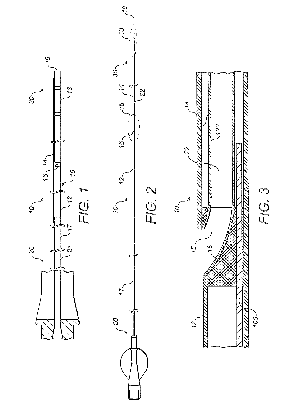
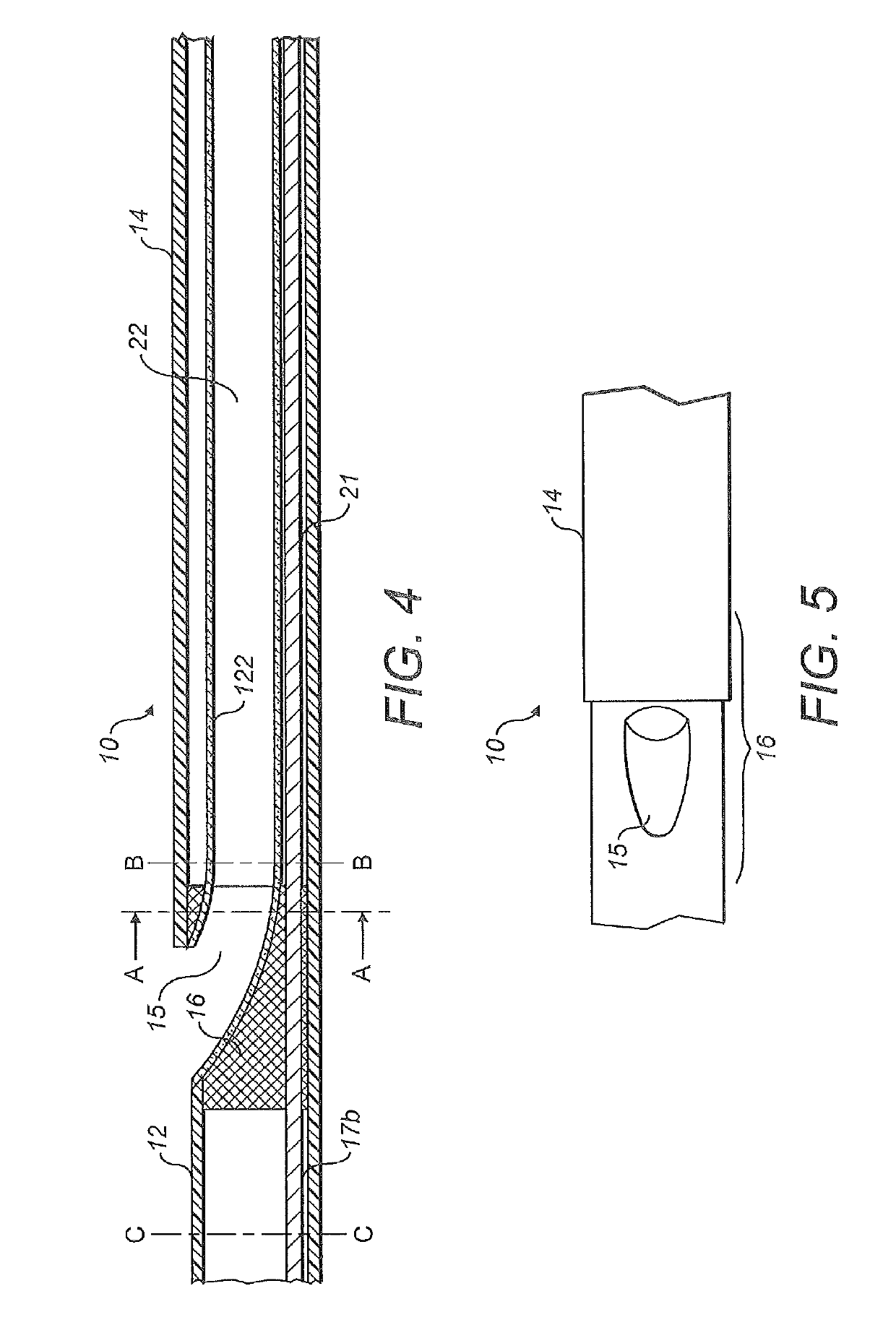
[0038]FIGS. 1 and 2 show a rapid exchange catheter. The tota...


PUM

PropertyMeasurementUnit
lengthaaaaaaaaaa
angleaaaaaaaaaa
angleaaaaaaaaaa

Abstract

A rapid exchange catheter includes a stiff proximal tube and a relatively flexible tapered distal tube, a guide wire tube being provided in the distal tube, with an aperture for access to the guide wire lumen being provided at the junction between the distal tube and the proximal tube, the tubes being bonded together at their junction.

Description

CROSS-REFERENCE TO RELATED APPLICATIONS[0001]This application claims priority of United Kingdom patent application Serial No. GB0911532.0, filed Jul. 2, 2009.TECHNICAL FIELD[0002]The present invention relates to a rapid exchange catheter. In particular it relates to a catheter that may be used in a rapid exchange system. The present invention also relates to an implant deployment assembly including a catheter.BACKGROUND ART[0003]Catheters have found widespread use in medical procedures, such as percutaneous transluminal coronary angioplasty (PTCA) or for delivery of an implant such as a stent, a stent-graft or an occlusion device. Most catheters are guided to the application site by sliding the catheter along a guide wire, which has been carefully advanced and arranged within the patient. During advancement of the catheter along the guide wire, it is important to keep the guide wire steady. Ordinary catheters are guided to the application site in a patient by sliding the catheter al...

Claims


Application Information

Patent Timeline
Patent Type & Authority Patents(United States)
IPC IPC(8): A61M25/00A61F2/958A61M25/10A61M25/01
CPCA61M25/0023A61F2/958A61M25/0015A61M2025/0183A61M25/0054A61M25/10A61M29/02
Inventor AGGERHOLM, STEEN
Owner COOK MEDICAL TECH LLC
Learn More