

Method for operating a hydraulic brake system of a motor vehicle and a hydraulic braking system
a technology of hydraulic brake system and motor vehicle, which is applied in the direction of braking system, braking action transmission, transportation and packaging, etc., can solve the problems of the operability of the brake pedal, and further limited, so as to reduce the effect of the physical limitations of the braking system, limiting the rate of vehicle deceleration, and preventing further pressure build up in the braking system
- Summary
- Abstract
- Description
- Claims
- Application Information
AI Technical Summary
Benefits of technology
Problems solved by technology
Method used
Image

Examples
Embodiment Construction
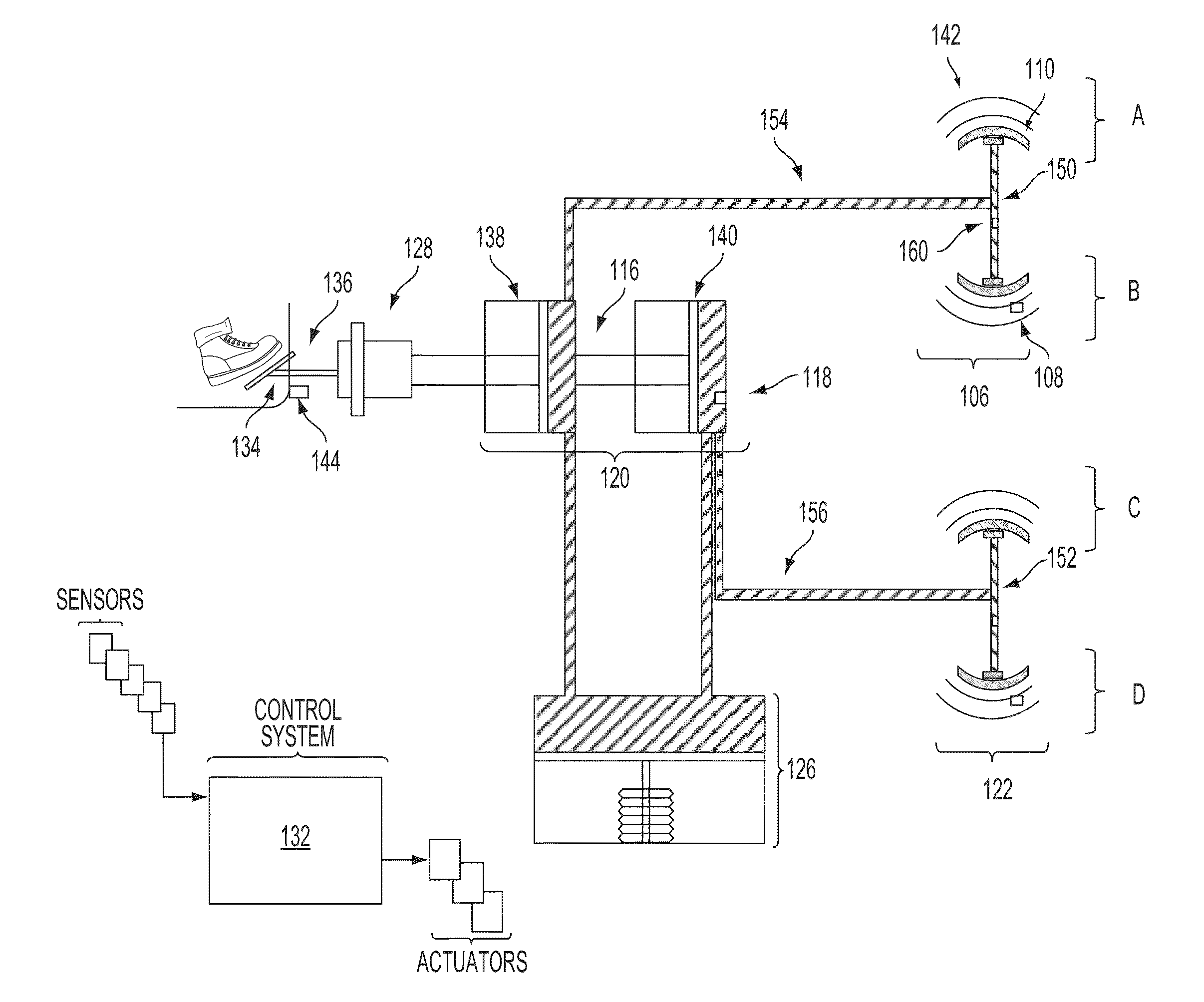
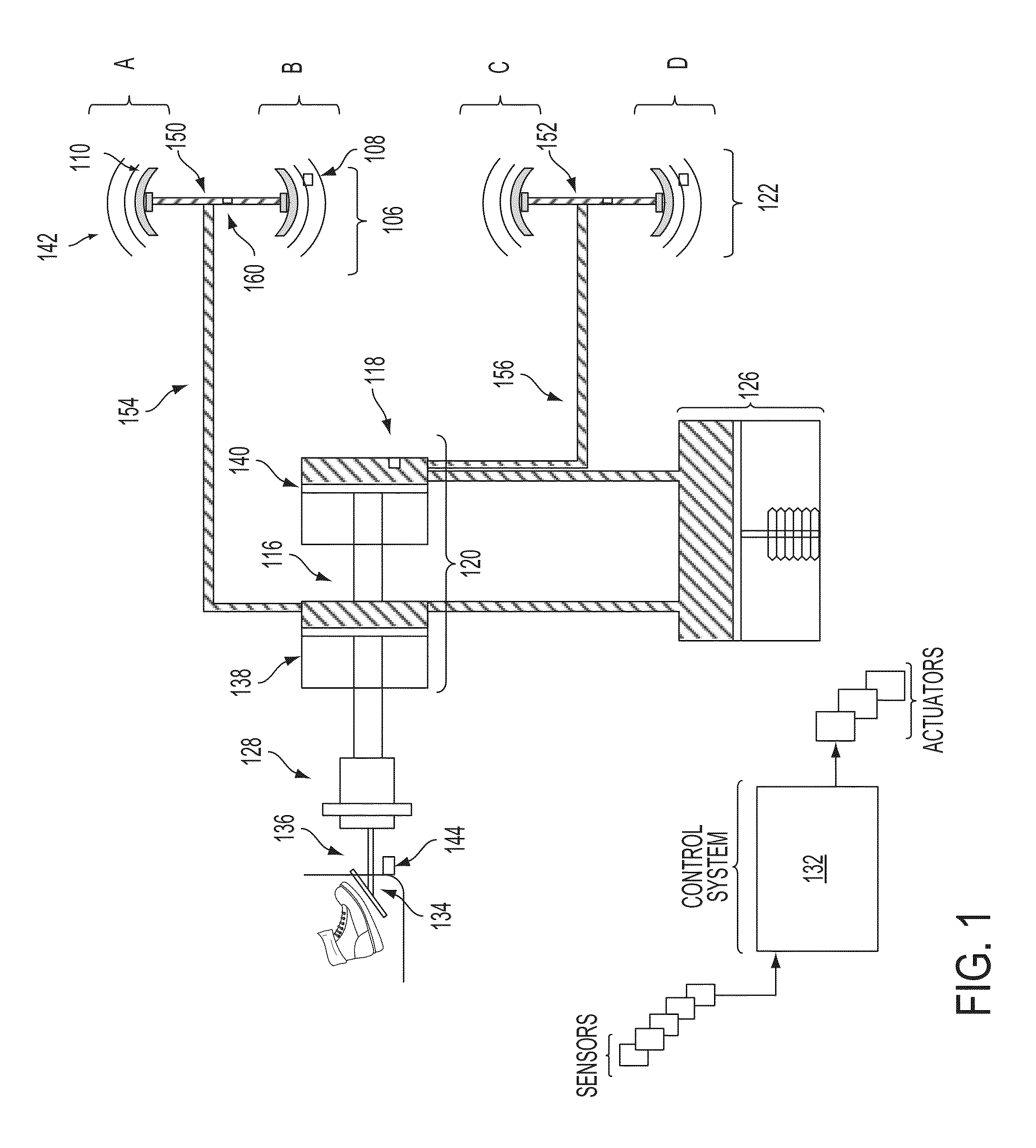
[0013]The following description relates to systems and methods for modulating the pressure applied by the actuation of a brake pedal in a hydraulic braking system of a motor vehicle. A hydraulic brake system, such as the system schematically illustrated in FIG. 1, in a motor vehicle may include a master brake cylinder that can be actuated by means of a brake pedal in order to generate brake pressure to one or more wheel brake devices in fluid-flow communication with the master brake cylinder. The brake system may include or interact with a control system which may be embodied to receive a signal from sensors to actuate an additional pressure generating device within the brake system. These sensors may be utilized to determine if a minimum residual actuation travel of the brake pedal is available and, by way of the control system, initialize and control the build up additional brake pressure in the master brake cylinder or in addition to the master brake cylinder by the additional pr...
PUM
 Abstract
Description
Claims
Application Information