
Method for operating a hydraulic brake system of a motor vehicle and a hydraulic braking system

a technology of hydraulic brake system and motor vehicle, which is applied in the direction of braking system, braking components, transportation and packaging, etc., can solve the problems of limiting the operability of the brake pedal, and further so as to reduce the effect of the physical limitations of the braking system, prevent further pressure buildup in the braking system, and limit the rate of vehicle deceleration

Active Publication Date: 2015-04-14
FORD GLOBAL TECH LLC
View PDF4 Cites 0 Cited by
  • Summary
  • Abstract
  • Description
  • Claims
  • Application Information

AI Technical Summary

Benefits of technology

The patent describes a system for controlling the pressure applied by the brake pedal in a hydraulic braking system of a motor vehicle. The system uses sensors to monitor the position of the brake pedal and the master brake cylinder. By monitoring these signals, the system can adjust the pressure in the master brake cylinder to maintain a minimum residual actuation travel of the brake pedal. This allows for increased safety and reduces the effect of gas bubbles in the system. The system can also include an additional pressure generating device to increase the braking force generated by the brakes. Overall, the system improves the performance and safety of the braking system.

Problems solved by technology

It is further limited by the operability of the brake pedal and the ease in which the motorist can negotiate between acceleration pedal and brake pedal.
Brake pedals can therefore reach their physical travel limits by hitting the vehicle floor pan, or the master cylinder hits its end stop, preventing further pressure build up in the braking system, limiting the rate of vehicle deceleration.

Method used


Image

  • Method for operating a hydraulic brake system of a motor vehicle and a hydraulic braking system
  • Method for operating a hydraulic brake system of a motor vehicle and a hydraulic braking system
  • Method for operating a hydraulic brake system of a motor vehicle and a hydraulic braking system

Examples


Embodiment Construction

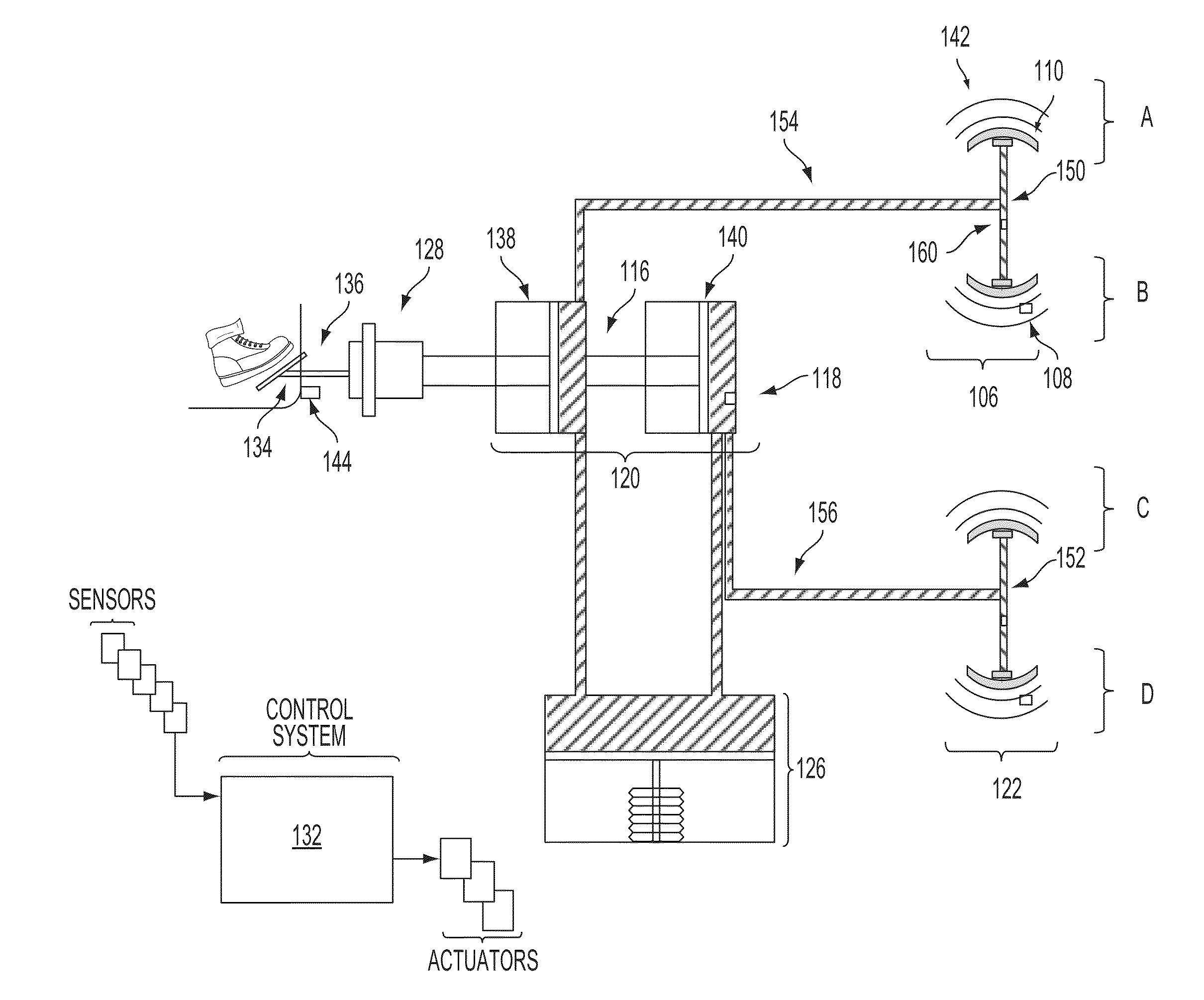
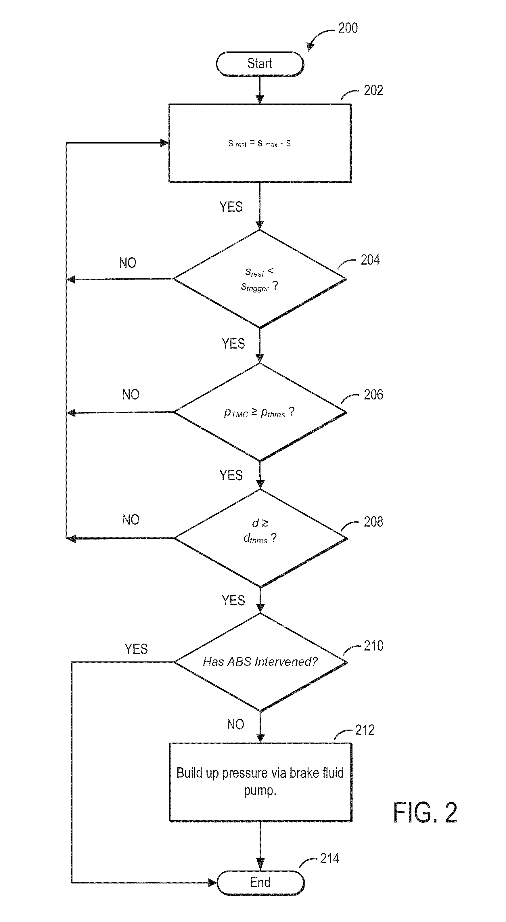
[0013]The following description relates to systems and methods for modulating the pressure applied by the actuation of a brake pedal in a hydraulic braking system of a motor vehicle. A hydraulic brake system, such as the system schematically illustrated in FIG. 1, in a motor vehicle may include a master brake cylinder that can be actuated by means of a brake pedal in order to generate brake pressure to one or more wheel brake devices in fluid-flow communication with the master brake cylinder. The brake system may include or interact with a control system which may be embodied to receive a signal from sensors to actuate an additional pressure generating device within the brake system. These sensors may be utilized to determine if a minimum residual actuation travel of the brake pedal is available and, by way of the control system, initialize and control the build up additional brake pressure in the master brake cylinder or in addition to the master brake cylinder by the additional pr...


PUM


Abstract

A method for operating a hydraulic brake system of a motor vehicle, comprising a pressure generating device used to build up additional brake pressure in a master brake cylinder or in addition to a master brake cylinder and in opposition to further pedal actuation wherein the additional pressure is a function of the pedal actuation travel distance. A method that reduces the limitations of a braking system's physical parameters on the build-up of additional braking pressure.

Description

CROSS-REFERENCE TO RELATED APPLICATIONS[0001]This application claims priority to German application number 102012200007.0 filed on Jan. 2, 2012, the entire contents of which are hereby incorporated herein by reference for all purposes.SUMMARY AND BACKGROUND[0002]Modern automobiles regularly employ hydraulic braking systems. In this system the pressure applied to the brake pedal displaces a piston in a pressurized fluid chamber or master brake cylinder. In a dual circuit braking system pressure is generally applied to two braking systems via a tandem master cylinder, comprising two pressure chambers coupled, in series, by a secondary piston. A braking force amplifier may be incorporated into the master brake cylinder generating additional force proportional to the actuation of the brake pedal acting in the direction of actuation. The master brake cylinder is generally coupled to one or more wheel brake cylinders via hydraulic lines. The subsequent displacement of brake fluid transmit...

Claims


Application Information

Patent Timeline
Patent Type & Authority Patents(United States)
IPC IPC(8): B60T8/88B60T8/44B60T11/28B60T13/16B60T13/66B60T17/02
CPCB60T13/161B60T17/02B60T8/442B60T8/445B60T11/28B60T13/66B60T7/06B60T13/662
Inventor SVENSSON, THOMASMOORE, IANDANIELS, RUDOLF
Owner FORD GLOBAL TECH LLC
Learn More