Drilling stabilizer

a stabilizer and drilling technology, applied in the direction of drilling rods, drilling pipes, drilling casings, etc., can solve the problems of buckling of drill strings, inability to remove wells, and stuck drill strings, etc., to reduce inventory requirements, improve drilling efficiency, and facilitate attachmen

Inactive Publication Date: 2008-01-03
COBB ARCHIE A
View PDF2 Cites 2 Cited by
  • Summary
  • Abstract
  • Description
  • Claims
  • Application Information

AI Technical Summary

Benefits of technology

[0019]It is an object of the stabilizer of the present invention to provide a stabilizer which can be manufactured without the need for welding and heat treatment.
[0020]It is another object of the present invention to reduce the inventory requirements associated with stabilizers by having centralizing members of various ring gauge diameters which may be quickly and easily attached to a single tubular body member.
[0021]It is yet another object of the present invention to provide a stabilizer wherein the flow of mud and drill cuttings is optimized and the incidence of balling up of chips is reduced.
[0022]It is a yet another object of the present invention to provide a stabilizer wherein stabilizer bodies having different ring gauge sizes can be easily and efficiently changed without the need to remove a tubular member from a drill string.
[0023]It is yet another object of the present invention to improve drilling efficiency by reducing rotational and sliding friction between a stabilizer and the well bore.
[0024]It is a further object of the present invention to provide a stabilizer which easily negotiates curves and bends in the path of the well bore, and reduces the incidence of sticking in a well bore.

Problems solved by technology

When drilling in open hole, the drill string may be forced against the wall of the well bore by the pressurized drilling mud with sufficient force that the drill string and down hole tools become stuck and cannot be withdrawn from the well.
During drilling operations, drill strings are frequently loaded in torsion and compression, thereby making such drill strings subject to buckling.
In addition to other problems, such drag can prevent weight from being transferred to a down hole drill bit.
However, space on drilling rigs is usually limited, especially on offshore drilling rigs.
Therefore, maintaining a large inventory of stabilizers is both expensive and inefficient.
Elongate stabilizer blades of the existing art create significant resistance to rotation and to axial “sliding” of the drill string, thereby reducing the efficiency of the drilling process.
Elongate stabilizer blades are also subject to becoming stuck against the wall of a well bore.
Moreover, drill cuttings generated during the drilling operation tend to “ball up” between the blades of the stabilizer as they are carried up the annulus, thereby restricting the flow of mud up the annulus.
Prior art welded stabilizer blades also present various problems.
The welding process can be expensive and requires heat treatment procedures which, if done improperly, may reduce the integrity of the tubular body member.
Further, welded members must be inspected periodically using an approved method of non-destructive testing; such inspection can be expensive and must be performed by highly trained personnel.

Method used


Image

  • Drilling stabilizer
  • Drilling stabilizer

Examples


Embodiment Construction

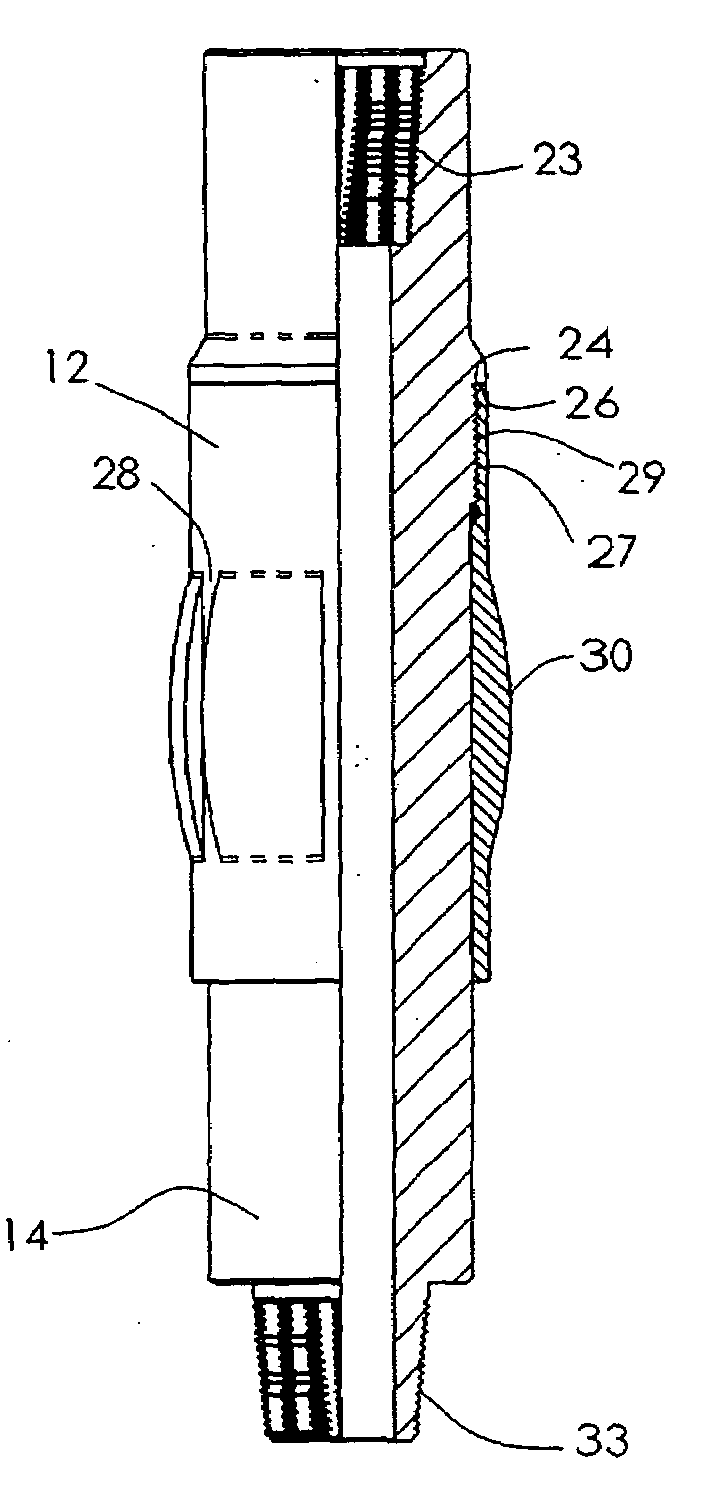
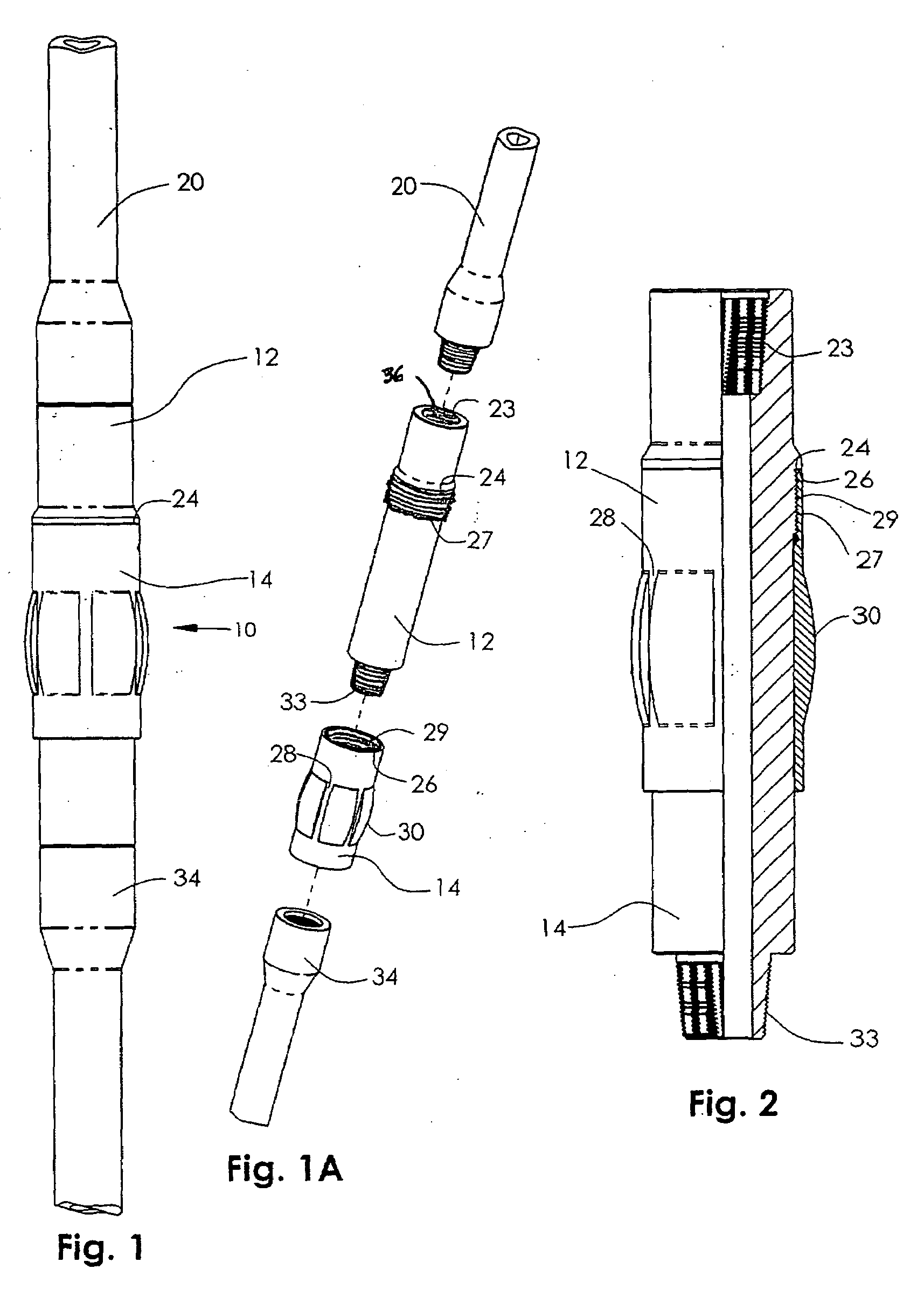
[0028]Referring to the drawings, FIG. 1 depicts the stabilizer assembly 10 of the present invention installed in a conventional drill string. Stabilizer assembly 10 comprises tubular body member 12 and centralizing member 14. In FIG. 1, stabilizer assembly 10 is incorporated in a conventional drill string between upper drill pipe section 20 and lower drill pipe section 34.

[0029]Still referring to FIG. 1, tubular body member 12 has external shoulder 24 around as the outer surface of said member 12. In the preferred embodiment, said shoulder 24 is situated a sufficient distance from the top of body member 12 to accommodate drill pipe tongs, which are large wrench-like devices used to tighten and loosen threaded drill pipe connections on drilling rigs.

[0030]Referring to FIG. 1A, which depicts an exploded view of FIG. 1, body member 12 has a female “box” threaded connection 23 at its upper end and male “pin” threaded connection 33 at its lower end. Box connection 23 mates with the threa...


PUM


Abstract

A stabilizer used to centralize drill pipe in the drilling of wells, such as oil and gas wells, having a replaceable member with a contoured outer surface and specifically designed flow paths.

Description

CROSS REFERENCES TO RELATED APPLICATIONS[0001]NoneFEDERALLY SPONSORED RESEARCH[0002]Not ApplicableSEQUENCE LISTING OF PROGRAM[0003]Not ApplicableBACKGROUND OF INVENTION[0004]1. Field of Invention[0005]This invention relates to an apparatus utilized to stabilize and centralize drill pipe and / or other tubular goods during the drilling of wells, such as oil and gas wells. More particularly, this invention pertains to a drilling stabilizer having a removable stabilizing member having a contoured outer surface and at least one flow path.[0006]2. Description of Related Art[0007]During the drilling of wells, such as oil and gas wells, a drill bit is typically located at the distal end of a length of drill pipe known as a “drill string,” and rotated to penetrate into the earth's crust. The drill string generally comprises a number of individual joints of drill pipe and / or down hole tools joined end-to-end to form a continuous length of pipe. In many cases, the outer diameter of the drill bi...

Claims


Application Information

Patent Timeline
Patent Type & Authority Applications(United States)
IPC IPC(8): E21B17/10
CPCE21B17/1078
Inventor COBB, ARCHIE A.
Owner COBB ARCHIE A
Why Eureka
Try Eureka